Search... ELectronics :

Very Simply 10 Watts Stereo Power Amplifier-TDA2009A


Here are a power amplifier with TDA2009A integrated circuits produced by 10 +10 W stereo amplifier (see figure). As a result of ASIC, making her the production becomes very simple, the performance is not bad.

Her main performance characteristics in the table below.

Power Supply Voltage: DC 8-24V/1-2A
Power Output:
  1. 10W RMS / channel, 4 ohm load, 24V/DC power;
  2. 6W RMS / channel, 8 ohm load, 24V/DC power;
  3. 4W RMS / channel, 4 ohm load, 12V/DC power.

S/N: >75dB/10W output
Frequency response: 10Hz-50kHz,-3dB
Gain: 36dB
Input Level: 100mV Full output power

Schematic and Prototype:


Principle and production elements:

C1, C2 as the input capacitor, C10, C11 for the output capacitor. C6, C7 for the feedback capacitance. R1/R2, or (R3/R4) control the amount of feedback. Amplifier gain is equal to 1 + (R1/R2) = 68, or 37dB. C4, C5 for the power supply filter capacitor. The device maximum supply voltage of 28V. Hours of work required to add TDA2009A heat sink, and should pay attention to the power lines and then the choice of speaker wiring. Input should use shielded lines and as short as possible. Welding TDA200A not take too long when you pay attention, action to be fast, but if you want their full integration with the circuit board.

Mini Subwoofer 5″ – 6″ BandPass 4th Order Isobaric

The order of 4 or sealed rear chamber bandpass system is essentially a system of watertight enclosures with the addition of an acoustic filter for the driver. The resulting system usually provides a lower cut-off frequency, the compromise that a larger case. The space can be reduced by two drivers in isobaric configuration.

4th-order bandpass systems generally show better able to handle the functions that the other major systems are considered. The transient response and is second only to the sealed enclosure systems, making it a good choice for subwoofer applications.

Since all output 4th order bandpass system is via the port, the largest diameter possible for the port area should be used to minimize noise from the port. The ports must be incinerated where possible, for the same reasons.


4th order Ssobaric Subwoofer Box Design

The 4th order bandpass system rarely allows a perfect bandpass response - there is usually an out-of-band noise present in the production. A notch filter can be used simply to reduce the noise as audible. Otherwise, a lowpass filter used in series with the driver, but the in-band response system may be affected if this approach is taken.

As the speaker sound 4th order band pass issued by the openings or ports on the port side of the box, the port noise inevitable.

This unwanted noise can be minimized by a notch filter and the largest diameter possible for the port of the area should definitely be used. Another option is to burn the ports of the 4th order bandpass room as this will certainly help to reduce unwanted extra from the subwoofer.

Mini SubWoofer Power Amplifier clik for detail

WOOFER / MID MODEL - 5MP60 / N

Specifications
Nominal Basket Diameter 5 "/ 125mm
Impedance 8 ohm
RMS Power 50 Watts
Program Power 100 Watts
Frequency response 50Hz - 12.0kHz
Sensitivity (1W/1m) 91dB
Voice Coil Diameter 1 "/ 25.8mm
BL Factor 6.4 N / A
Voice Coil Length 14 mm
Air Gap Height 6mm
X Damage (peak to peak) 20 mm
Magnetic Assembly Weight 2.2 lbs / 1.0 kg.
Edit Information
Diameter 5.28 "/ 134mm x 5.28" / 134mm
Bolt Circle Diameter 5.4 "/ 137mm
Baffle Cutout Diameter --
- Front Mount 4.72 "/ 120mm
Many of the 4 mounting holes
Volume displaced by driver, 019 m 3 / .5 liter
Total Depth 2.68 "/ 68mm
Net weight 2.64 lbs / 1.2 kg.
Weight 2.8 lbs / 1.27 kg.
Materials
Basketball aluminum diecast
Polypropylene cone
Rubber Surround
Voice Coil Wire Copper
Ferrite
Thiele-Small Parameters
Resonance Frequency (FS) 60 Hz
Impedance (Re) 5.33 ohms
Coil Inductance (Le) 0.4 mH
Mechanical Q (Qms) 1.604
Electrical Factor (Qes) .35
Total Q (Qts) .29
Comp. Equivalent Vol. (Vas) 35 FT3 / 9.8 Liter
Voice Coil Overhang (Xmax) 4.0mm
Reference yield 5%
Volume Displacement 34 cm3

22 Watts Mini Subwoofer Circuit TDA1516 with Adjustable Frequency

The subwoofer is a subwoofer or a speaker to reproduce low frequencies, devotee of 20 Hz to 150 Hz electronic circuit diagram below shows the details of a scheme of the main amplifier TDA1516 22 watt in 4 ohm car subwoofer driver. This device is designed for an existing stereo amplifier, often requires adding another blow to the music of driving a subwoofer.

The amplifier uses BTL is a good and cheap ((Bridge Tied Load channels) 13-pin IC TDA1516 from Philips is now NXP Semiconductors), which may provide a small number of components and 22W at 4 ohm load voltage 12 volt car battery default.

The device consists of several parts: the name of the potentiometer, dual-linear motion potentiometers, 1/4W resistors, capacitors, electrolytic 25V, 63V Polyester capacitors, LED, 100 mA NPN transistor, dual BIFET Op-Amp, 24 W BTL car radio RCA audio input amplifier and two speakers 4 ohm or 8 ohm woofers in isobaric parallel wiring.


DIY 12 volt car project Subwoofer frequency low-pass filter circuit and BTL Amplifier TDA1516

The signals from the line outputs for stereo mixing amplifier input drive, and taking into account the level of the signal to the buffer and can be reversed IC1A phase SW1. Such control may be useful to the subwoofer in phase with the speaker of the existing car radio.

Then, a variable frequency 12dB/octave-pass low IC1B, the components of the Q1 and then you can pass the low frequency of 70 Hz or 150 Q2, R17 and C9 form a voltage stabilizer to facilitate access and filtering circuit to prevent track of the services given power at a low level positive.

LPF subwoofer and amplifier parts list:


Potentiometer
P1-10K
P2-22K

Resistor
R1, R4-1K
R2, R3, R5, R6-10K
R7, R8-100K
R9, R10, R13-47K
R11, R12-15K
R14, R15, R17-47K
R16 6K8
R18-1K5

Capacitor
C1, C2, C3, C6-4μ7 25V
C4, C5-68NF 63V
C7 33nF 63V
C8, C9 220μF 25V
C10 470nF 63V
C11 100nF 63V
C12 2200uF 25V

Diode
D1 LED Lamp

Transistor
Q1, Q2 BC547

IC
IC1-TL072 Op-Amp
IC2-TDA1516BQ Car Amplifier 24 Watt BTL

Switch
SW1-Toggle SPDT
SW2-Toggle SPDT

RCA Jack
J1, J2 RCA Audio Input

SubWoofer Drive Unit
4-ohm woofer driver or two 8 ohm woofers connected to Isobaric

Isobaric 4th order Bandpass Subwoofer Box Design

The fact that we need a subwoofer means that something is missing in the performance of the main speakers. This is not surprising, since the speakers unfortunately have to coexist with families, women and companions, leading to the inevitable Compact, stand-mounted speaker. Modern, compact speakers are excellent performances, but there is no further away from the laws of physics, small box = bad bass. So, modern speakers designed for a response in the low-limit?

User isobaric subwoofer on the Altec Lansing FX4021 and FX5051


4th isobaric subwoofer box design

The subwoofer is a bit of a word misnomer. It includes sub-audio course can not hear you. We mean really low sound. This does not mean we can not "collect" the sub-audio frequencies. The body can not perform under the form of audio-frequency vibrations and can strengthen the reality of the listening experience. There is usually little more low audio below 20Hz in most of the music.

The only (not electronic), an instrument can produce something in this Church is the body 16.67Hz. Even if this body is equipped with the solid pipe is usually filled with something to prevent the building collapsing around!

For practical reasons we can arrange to 20Hz as the lowest audio frequency that we want to reproduce, may be less than that, the boxes are often quite large. OK. So who determines the lowest frequency we want the subwoofer to handle, but what about the highest frequency?
It is easy to match the response of the existing speakers.

In my case, my speakers are-3dB at 47Hz. That is a lot better than most small speakers, 70-80Hz at-3dB is fairly typical. Ideally the subwoofer to be on the same-3dB frequency. It is easy acheivable a low-pass electronic filter. These can easily be made adjustable to fit almost all existing stakeholders.

Why only one subwoofer, we have two for stereo? The answer to this depends on how the human ear perceives direction. The brains very carefully compares the phase of sounds in the left ear or right and take a decision on this basis.

At high frequencies, the distance between the ears is an important part of the wavelength and the phase difference is large. Because the frequency is reduced, the distance between the ears small compared to the wavelength.

The phase difference is reduced making it difficult for the brains towards the sound calculates. It is not by any means the whole story, the ears also use the level difference and the slight head movements to better determine the direction. Below 200Hz, the human auditory system is almost fully able to determine direction, so it does not matter if the bass is in stereo, mono or even in the room where it originated.

Thus, a subwoofer is all you need. It is normal that the sum of the left and right channels within the subwoofer, so no information is lost. Joint Stereo is often used in the MP3 coding scheme. The low frequencies are encoded in mono, stereo at higher frequencies.

I have several cheap 180 mm / 6.5 "drives and carefully measured their parameters. This step is crucial in this kind of design that even small errors affect the frequency response drastically.

I used my speaker WinISD and added to the database to track the response and the size of the box to calculate. Compromises are necessary in this kind of design. You can find a good performance and a very narrow bandwidth or poor performance and a wider bandwidth. What is acheivable entirely dependent on the properties of the drive. I was fortunate in that my 3 pounds produced a pilot-3dB bandwidth of 29-76Hz. I can not change, but I could filter out the high-end to match my existing speakers.

I decided to use a configuration with two drive Isobaric back to back. This has the advantage of reducing by half the required volume of the two halves of the bandpass enclosure.

One effect of the tax Isobaric half volumes needed in contrast to cases where a driver was used. Another is that the port setting remains the same, but half of the volume, equivalent to a doubling of the port.

Note in the above table, the port is 401mm long. There is no place for him in the cavity 11 liter before with a little thought Latteral was necessary for the host. Some ideas are not at this point if the port can not be physically made to adapt. In this example, I solved this problem with the design.

Subwoofer Box Spec:


Number of cores 2 (used as an installation isobaric) 4th Order Bandpass Box Type Box dimensions for chamber 11.0 liters 24.5 liters Achterhuis Port tuning frequency of 46.56 Hz Wind 1 Wind -> Front Room from 0401 to 0060 m long x 0.060 m square

Power Amplifier Gainclones more Gainclones Power Amplifier

2x25 Watt LM1875 Gainclone Amplifier


2x50W LM3875 Gainclone Amplifier


2x56W LM3876 Gainclone Amplifier


2x68W LM3886 Gainclone Amplifier


2x50W Tube Gainclone Hybrid Amplifier


Build Power Amplifier LM3876, Simply and Powerfull Power Amplifier

The chip on which the amplifier is based, a Type LM3876, is a member of the Overture family from National Semiconductor, All members of this family are pin-compatible and mutually interchangeable. They are typified by an internal protection (called SPIKE). In practice, the diftection ference between them is the power output. The series was described on the basis of the LM3886 in an earlier issue*.

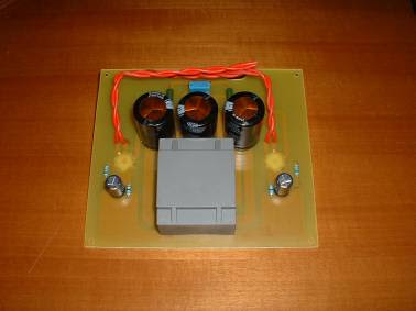
The PCB has been designed so what it can accommodate the LM3876 (50W) as well as the LM3886 (150W). Because of this, pin5 of the IC on the board is connected to the positive supply line. This connection is not needed for the LM3876, since its pin5 is not (internally) connected (NC).

The IC is located at the side of the board to facilitate fitting it to a heat sink as shown in the photograph.

An important aspect for optimum performance is the decoupling of the unregulated supply lines by C 7-10. All earth connections go to a single terminal on the board.

Air-cored inductor L1 consists of 13 turns of 1mm dia. enamelled copper wire with an inner diameter of 10mm. The completed inductor is pushed over R7 and its terminals soldered to those of the resistor.

All electrolytic capacitors must be mounted upright. The amplifier can be muted with a single-pole switch connected to the MUTE input (pin8). This function is enabled when the switch is open. If muting is not required, solder a wire bridge across the mute terminals on the board.

Boucherot network R6-C6 is not normally required in this application, but provision has been made for it for use in other applications.

According to the manufacturers, both chips are optimalized for a load of 8 Ohm. The output power is lower when a 4 Ohm load is used or when the supply voltage is reduced. When a 4 Ohm load is used, the SPIKE protection becomes active when the supply voltage is about 27V, resulting a in a reduction of the power output to 10W. This means that it is not advisable to use loudspeaker with an impedance < 8 Ohm.

For best result you can expand power amplifier using BPA-200 Amplifier


Part list

Resistor:
R1, R3 = 1 k
R2, R4, R5 = 18k
R6 = see text
R7 = 10R, 5 Watt
R8, R9 = 22k

Capacitors:
C1 = 2.2 uF
C2 = 220 uF, 160 V
C3 = 22 uF, 40 V
C4 = 47 pF
C5 = 100 uF, 40 V
C6 = see text
C7, C8 = 100 nF
C9, C10 = 1000 uF, 40 V

Inductors:
L1 = 0.7 uH - see text

Integrated circuits:
IC1 = LM3876T

Miscellaneous:
Heat sink for IC1 < 1.5 K W-1
Single-pole switch - see text


Schematic and PCB Layout LM3876

Build Power Amplifier LM4780 with BPA-200 Amplifier

This is design is very similar to the National Semiconductor BPA-200 (Bridge/Parallel Amplifier) which uses 4x LM3886 per channel and an input buffer:


Nothing Special in design but usefully for more watts!
My one will use 2x BrianGT LM4780 kits and a balanced line driver to bridge them, like this:


The LM4780 is a stereo audio amplifier capable of typically delivering 60W per channel of continuous average output power into an 8 load with less than 0.5% THD+N from 20Hz - 20kHz.
The LM4780 is fully protected utilizing National's Self Peak Instantaneous Temperature (°Ke) (SPiKeTM) protection circuitry. SPiKe provides a dynamically optimized Safe Operating Area (SOA). SPiKe protection completely safeguards the LM4780's outputs against over-voltage, under-voltage, overloads, shorts to the supplies or GND, thermal runaway and instantaneous temperature peaks. The advanced protection features of the LM4780 places it in a class above discrete and hybrid amplifiers.

Each amplifier of the LM4780 has an independent smooth transition fade-in/out mute.
The LM4780 can easily be configured for bridge or parallel operation for 120W mono solutions.


The total effect is (2x LM3886's paralleled) x2 Bridged and should give approx 225 watts into 8 ohm and 335 watts into 4 ohm when used with a sufficient power supply.

The line driver part is based on the DRV134 and a PCB from digi01, you can see the details here.

In the end mine was dual mono in a recycled amp case using 2x 300VA (18VACx2) toroidal transformers, 54,400uF of capacitance per channel with a snubber. The DRV134s add 6dB of gain so I set the LM4780s to about 16x gain to compensate (they are set to 33 normally). I get no DC offset, no hum, no crackle or thump on turn on or turn off, silent as.

Pics.....


DIY Cat5 Speaker Cables

These are perfect speaker cables for my brother speaker. I build use AMP Cat6 cables, for detail view here.


AMP Cable Cat6


TwistPair in TwistPair Cable Cat6

 
Ilustration wiring cable speaker using cable cat6

Perfect Sound Granite DIY Speaker Project

I have been build this speaker for my brother, these are do-it-yourself (DIY) speakers that and using granite for the speaker box. I listen this speaker, That's Great Perfect Sound, nearly linear reproduction sound. Great Job Man!. Source Perfect Sound Granite DIY Speaker Project.


DIY Granite Speakers with Seas G17REX/P and 27 TFFC Drivers


Speaker Project Summary
External box dimensions 240 x 350 x 280 mm. Internal box dimensions 200 x 310 x 240 mm. Box material 20 mm thick black granite (Nero Assoluto). Weight 35 kg.
Enclosure volume 14.9 L. Bass reflex enclosure tuned to 45 Hz. Port length 160 mm
Input power 80W. Sensitivity 87.5 dB. Transmission bandwidth 40Hz - 20kHz. Impedance 6 ohm.


Seas Granite Speaker Enclosure Plan

Seas Loudspeaker Drivers
The drivers selected for this loudspeaker system are from Seas who has been producing speaker drivers for over 50 years. The tweeter is the Seas 27 TFFC which has a fabric dome. The Sonolex lightweight fabric dome has high consistency and provides excellent stability against variations in air humidity. The stiff and stable rear chamber allows for a moderately low crossover frequency (~2500kHz). This made the Seas 27 TFFC tweeter the right choice for our granite loudspeaker project.

The woofer we used is the Seas G17REX/P. The woofer consists of a fiber glass cone, a bullet shaped phase plug and a high loss rubber surround. These are carefully matched to each other resulting in smooth frequency response.


Speaker Box and Crossover Design
The speaker box and crossover network were designed by M.Janura and K.Sýkory using the LspCAD speaker design software package. A volume of 15L (dimensions 220 x 350 x 250 mm) and a tuning frequency of 45 Hz was used for the speaker box. The dividing frequency is 2.5kHz and the drivers are connected in phase. The crossover schematic and modeled frequency response are shown below.

Calculated Speaker Box Frequency Response - Seas G17REX/P Woofer


Crossover Schematic - Seas G17REX/P Woofer and 27 TFFC Tweeter


Crossover Schematic - Seas G17REX/P Woofer and 27 TFFC Tweeter

The components used in the crossover dividing network are from TESLA. I think that the people in the former Czechoslovakia were able to produce high quality components, but you may use your favorite type. The condensers (capacitors) used in crossover are MKT type - we did not use bipolar condensers because they have disadvantages that I won't further specify. The inductors are air core.

Sound

I was knocked off my feet with the sound after the first track we played: Everlast - Folsom Prison Blues by the legendary Johnny Cash. The song tested bass response of the speakers. We didn't expect such deep and accurate bass from small speakers. The speakers deliver very detailed sound (soft treble and great imaging). They play rock music aggressively and classical music with emotion. As we say: "they play like HONEY" (it means - brilliant) and they look great too.

I would like to thank to Marian Mózer and everyone in the team for their effort and for the job well done. The loudspeaker system is designed by M.Janura and K.Sýkory - named Besie 1.

We understand that most of you will not be able to make speaker boxes of granite. If you are interested in speakers made from granite, please send me an email and we may be able to help you. Thank you and I hope you enjoyed our project.

Seas Granite Speakers

Single Ended Class-A Power Amplifier using 6C45Pi

The valve itself, have a simple circuit enviable any transistor amplifier, however, not many projects that employ a single active component. This construction philosophy, I like to call it minimalism.

If one speaks of minimalism, I think, that this project has all the credentials to qualify as such.

This is an amplifier cu, a final integrated (Compact) which employs a single tube (triode) signed 6C45Pi. To do this, could be used several tubes, including 437A, E55L (pentode) and the fantastic and expensive EC8020.

Two lines must for this valve: The EC8020 has an exceptional linearity, high dissipation and trasconduttanza worthy of a power triode. All factors ideal for a good amplifier cu, were it not for the prohibitive price (on the ebay Offers easily exceed one thousand dollars!).

6C45Pi even if does not reach the performance of EC8020, performs the task with dignity. The cost is a couple of orders of magnitude lower and is currently produced by Electro Harmonix and is part of his series most valuable the Gold Pins.

Schematic Diagram

The circuit used setup is classic: single-ended. This choice leads to a lower power, an output transformer more expensive, but all will benefit, at least for my taste, the sound quality.


About nutrition, the first idea was to use, such as straightening, a valve, but with an excessive size of the Schottky diode and filtering capabilities have also obtained excellent results (Sonic).


PCB

Not many projects are implemented on printed circuit valve, but it is my strong belief that, 's addition to a more orderly construction, provides added value to the success of the project.

The layout is as follows:

A fundamental rule in the design of the board is to avoid any link mass, so you should use as much as possible in a star structure. Usually the star center coincides with the negative of the first capacitor filter.

Realization

The board:
PCB2-Single-Ended-Class-A-Power-Amplifier-using-6C45Pi
PCB1-Single-Ended-Class-A-Power-Amplifier-using-6C45Pi

I used the usual method of iron more HCl + H 2 O 2.

Four resistors are metal film for half a watt, those from 220ohm wire wound vitreous enamel coated 6W, the Panasonic FC Electrolytic low impedance. Alps potentiometer, then the diodes, as already mentioned, type Schottky 1000V 1.5 A.

The two TU are wrapped by the Company upon specific ATC Electronix: www.atcelectronix.com/ provides the following features:

Primary: 4000 ohms
Secondary: 6 ohms
Power: 10W
Grain-oriented core AC 0:35
Bandwidth: 15 Hz - 75 KHz
trafo-Single-Ended-Class-A-Power-Amplifier-using-6C45Pi


I like to use for my projects output transformers wound on specific, because I have the opportunity to obtain more than I seek., The kind Mr. E. Calabrese's ATC Electronix has been immediately available, we discussed the characteristics and came quietly meeting.

Mechanically, the TU are well made, sturdy, beautiful black ice caps, we see that there is the hand of a fan.

Some photos of finished:
Single-Ended-Class-A-Power-Amplifier-using-6C45Pi

The cabinet is birch plywood 10mm polished with wax. I like the effect that old yellow comes out. The photos do not make the idea of greatness, but it is really small, only 230 x 200 mm high 60mm (TU and TA excluded).

rear-Single-Ended-Class-A-Power-Amplifier-using-6C45Pi

I suggest to the speaker terminals, derived from a larval bi-wiring connections, it was a very economical way to get the four terminals, buying in bulk would have cost me more.

inside-Single-Ended-Class-A-Power-Amplifier-using-6C45Pi

The cable used for connections between RCA, potentiometer and card is excellent Belden.

Listening

A valve, one triode and yet it sounds. Thought of having to keep the volume potentiometer can to listen to a decent level, but it was not at all. The pot did not exceed half of the race than I shouted down ... but we are talking about a "paltry" Watts!. Certainly the BLH (FE108ESigma) have done their bit (90 dB / W efficiency).

I connected everything, turned on and my room was immediately filled with music. Main features: detail, depth and dynamics.

Everything I heard sounded really good, thanks not only 6C45Pi but also of TU ATC Electronix.

The Finaly I am deeply moved, usually happens at concerts and my master amplifier.

The Medes and the voices are spectacular. I listened to all possible kinds of vocal music. Each of them seem natural, male or female is.

From Jazz to Classical, dall'Acustica the Rock and anything there is in the middle, everything comes back perfect. This little amp is very transparent.

Having experienced the one-tube amplifier, I had the confirmation: I will be forever minimal! Few watts, or only a few components in the audio chain, single screw speakers, no cross-over, no feedback, just pure music!. An amp like this, a simple player, a pair of single screw is all that a person has (or should have) need. I am extremely satisfied, so much so that I could separate me from my SE with the 2A3 and not feel greatly missed.

Faults? Sure. The sensitivity is very high, indeed it is low for maximum power output must be driven by almost 5 Vpp. The dynamic is good, but only one watt is just for musicians. However, the little man is promoted with flying colors while remaining down to earth.

(Source: http://digilander.libero.it/giovannidefilippo/progetti/GDF-UNICO!/UNICO.htm)

Promitheus Hexfet Power Amplifier

Here you can find the whole article of the Elektor magazine of the new upgraded Hexfet amp. The new amplifier uses bigger output devices, IGBTs in T0-247 Package. It has more power and uses new technology transistors. These transistors are insulated gate bipolar transistors (IGBT). They have an input like a FET so the work with voltage and they handle current like a bipolar.
Look here for The IGBT or HexFet amp.

I used the same board for my own upgrade. I used the higher power supply voltage of the second edition for IGBTs but since I didn't like to use IGBTs (I am a great fan of MOSFETs) I went on and used bigger Mosfets instead in TO-247 P case. I used the IRFP250 and IRFP9250 from Intersil/Harris. They are very cheap and reliable. The IR are the same too. IGBTs are a lot more expensive. This amplifier is great with very good sound and a lot of power for all kinds of speakers.

Modification

The original design already allowed for a higher-output version, whence the duplicated holes for the output transistors on the printed-circuit board. At that time, advance information on the IGBTs was already available, but samples were not.

Although IGBTs are quite different from HEXFETs, the board for the original design can be used without any modification. In fact, the circuit has hardly changed. The most noticeable alteration is the replacement of the fuses in the source lines of the power FETs by emitter resistors for the IGBTs. The only other changes are in the value of two resistors in the compensating circuit of the input stage, of one in the quiescent-current circuit, and of one resistor and two capacitors in the protection circuit.

This means that anyone who has built the original HEXFET amplifier can quickly modify it to the upgraded version. One item needs to be replaced, however:
the mains transformer. After all, more power can not be obtained from the same supply voltage/current. The original transformer with 2×25 V secondaries must be replaced by one that provides 2×30 V at 3.75 A. This will result in a direct voltage of ±43 V.

Ceramic speaker driver amplifier design

Today's portable devices contributed to the smaller, thinner and higher efficiency of electronic devices needs. Now cell phones have become very slim shape, so that the traditional electric-powered loudspeaker has become a mobile phone manufacturers can create as many thin constraints. Ceramic or piezoelectric speakers is rapidly becoming a viable alternative to electric-powered loudspeaker device. These ceramic speakers (drivers) can be slim and compact package provides a very competitive sound pressure level (SPL), which most likely alternative to traditional electricity-powered loudspeaker voice coil.

Ceramic speaker driver amplifier circuit and drive the traditional electric-powered loudspeaker amplifier circuit compared to a different output drive requirements. The structural requirements for ceramic speaker amplifier is capable of driving large capacitive loads, can provide more current at high frequencies, while also able to maintain a high output voltage.

The characteristics of ceramic speakers

Ceramic speaker manufacturers use the technology is very similar to the manufacture of multi-layer ceramic capacitors used in technology. Compared with the electric-powered loudspeaker, the loudspeaker manufacturing technology enables manufacturers to more stringent control over the speaker tolerances. Speakers you want a unified and agreed upon the acoustic characteristics, the rigid structure of tolerance is very important.

As can be seen from the driver amplifiers, ceramic speaker impedance can be modeled as an RLC circuit, it comes with a large capacitor, this large capacitor is the main component of the model shown in Figure 1. For most audio frequencies, the ceramic speaker is manifested mainly capacitive. This capacitive characteristics of the speaker to express its resistance will decrease with increasing frequency. Figure 2 shows the similarity with 1uF ceramic capacitor speaker impedance and frequency characteristics.


The resistance also has a resonance point. Speakers at the resonant frequency above the audible most efficient point. Decrease in the impedance at 1kHz speaker expressed the resonant frequency.

Relationship Between Sound Pressure, Frequency and Amplitude

The two ends of the ceramic speaker to exert an alternating voltage can make the internal speakers of piezoelectric thin film deformation and vibration, the displacement distance is proportional to the input signal. Vibration of the piezoelectric film to promote the surrounding air, resulting in the sound. Improve the speaker can increase the voltage on the piezoelectric element deflection amplitude, resulting in a greater sound pressure and thus can increase the volume.

Ceramic speaker manufacturers maximum voltage tends to be used to mark their speakers, usually around 15Vp-p. Ceramic devices, said the largest voltage reaches the maximum extension. If the applied voltage is higher than the rated voltage does not produce a higher sound pressure, but it will increase the output signal distortion, see Figure 3.


By comparing the SPL and the frequency and impedance versus frequency curve can be seen in self-resonant frequency of piezoelectric speakers have a large SPL above the most efficient.

Amplifier Requirements.

Ceramic speaker manufacturers typically provides 14 to 15Vp-p of the point of maximum voltage to produce the greatest value of sound pressure. The question now becomes how to generate a single battery supply voltage of these voltages.

One way is to use switching regulators to raise the battery voltage is 5V. With a stable 5V voltage, the system designer can select a needed bridge-tied load (BTL) for single-supply amplifiers. Connected through the bridge can be automatically loads the voltage speaker to see double.

However, the BTL amplifier with 5V output swing theory can only give rise to 10Vp-p. The voltage is not enough to make ceramic speaker output value of the highest SPL. In order to generate higher sound pressure values need to be adjusted to a higher supply voltage.

Another method is to use the boost converter to the battery voltage rises to 5V or higher, but it also has its own problems, such as component size problem. Large peak inductor current will be restricted the size of the overall solution, because in the end of the inductor size must do in order for the physical size of large core is not saturated. Although the small size of the inductor-current market, there are, but the core's saturation current rating may not be sufficiently large to satisfy the high-frequency high-voltage-driven speaker when the load current demand required.

Because ceramic speakers at high frequencies with very low impedance, so when you drive the ceramic components to take into account high-current drive and to avoid the limit.

Chosen to drive the ceramic speaker amplifier must be large enough to drive current in order to avoid driving a large number of high-frequency component of signal-driven speaker into the current limiting mode.

Figure 4 is a Class G amplifier using the application circuit. Class G amplifiers are available multiple voltage rails: a high-voltage and a low voltage. Low-voltage rail used in the output small signal, when the output signal demands for higher voltage swing, the high-voltage rails were switched to the output stage circuit.


Thus, when the output signal is small, G amplifier efficiency than Class AB amplifiers high, due to a lower voltage rail. Because there is a higher voltage rail, G amplifier can still handle the peak transient signals.

Shown in the figure uses a MAX9788 on-chip charge pump to generate a negative voltage and the VDD opposite. The negative voltage rail only require a higher voltage output signal when added to the output circuit on the rail. Boost converter and method of using the traditional Class AB amplifiers, the device can be more efficient to drive ceramic speakers.

Loudspeaker manufacturers often recommend and ceramic speaker series with a fixed resistor (RL), as shown in Figure 4. The resistor in the signal that contains a large number of high-frequency components can limit the amplifier output current.

In some applications, if the restrictions sent to the speaker of the audio frequency response of bandwidth to ensure that the speaker is not short-circuit of the amplifier, you can not have this fixed resistor. Ceramic speakers currently on the market value of the 1uF capacitor of magnitude or so. Speaker as the impedance at 8kHz when 20W, at 16kHz when 10W. Future ceramic speakers may have a larger capacitance value, will force the signal amplifier at the same frequency to provide more current.

Ceramic speaker and the efficiency of electricity-powered loudspeaker.

The efficiency of traditional electricity-powered loudspeaker is easy to calculate. In electrical windings on the coil can be modeled as a fixed resistor in series a large inductor.

You can use the speakers resistance value calculated in accordance with Ohm's law to provide power to the load:

P = I2R, or P = VxI

The power consumption of the speaker coil heat.
As the ceramic speaker's capacitive characteristics, they are power consumption when not produce too much heat. According to the dissipation coefficient of ceramic components, such speakers consumption of so-called reactive power (blind power) is very small. Therefore, the consumption of reactive power generated when the heat is very small.

Can not use a simple calculation of P = VxI reactive power

Reactive power should it be calculated as follows:

P = (πfCV2) × (cosΦ + DF)

Where: c = capacitance value of the speaker; v = RMS driving voltage; f = the frequency of driving voltage; cos j = "current through the speakers, and speakers on the phase angle between the voltage"; Df = speaker dissipation factor, depends on the signal frequency and ceramic speakers ESR.

For an ideal capacitor, the voltage and current between the phase angle should be 90 degrees, while the ceramic speaker is mainly capacitive characteristics, so cos j is equal to 0, that is not part of the ceramic speaker's capacitive power. However, the non-ideal characteristics of ceramic materials will lead to lag behind the voltage on the speaker through the speaker of the current phase angle between them is not equal to 90 degrees. The ideal 90-degree phase shift and the actual difference between the phase shift is the dissipation coefficient. Ceramic speakers in the Df can be modeled as a small resistance, ESR, and an ideal capacitor in series. (Do not series resistance and the isolation between the amplifier and speakers to confuse resistance) Df is the target frequency, the ratio of ESR to the capacitive reactance (Reference 2 and 3):

DF = RESR / XC

For example, a 1.6uF capacitor and the speaker 1W ESR being 5Vrms, 5kHz signal when driving reactive power is:

P = (π × 5000 × 1.6e-6 × 52) × (0 + 0.05) = 31.4mW or 31.4mW.

Real Power

Thus, while the ceramic speaker itself does not like the electric-powered loudspeaker, as the actual power dissipation by thermal methods, but the driver amplifier output stage, and is located between the amplifier and speaker external resistor (RL) could give rise to heat (Figure 4).

An external resistor the greater the amplifier will generate more power, thus affecting the low-frequency response.

In the drive with a 10W series resistance of the ceramic speaker, we can see that the reactive power has little effect on total load power. Most of the power consumed by an external resistor, see Figure 5 shows the amplifier power and frequency curve.


Better low-frequency response for a smaller external resistor, but this will cause the amplifier output stage power consumption increase. Amplifier efficiency shows how much power consumption in the amplifier output stage. Driven right amplifier power, including class and G class D amplifier, including the demand for more efficient solution, due to the load formed by a number of series resistance, it will load on the network rather than the speaker to generate a certain power. Even if the efficiency of 100% of the amplifier, series resistance will be consumed is supposed to give the speaker power.

In this simple example, 5kHz provided to the load point of the total power is 515mW. Efficiency of 53% of the amplifier will consume 457mW of power. The necessary power amplifier the size of the device can determine the size of the package used. If you must use high-frequency sine-wave-driven speaker, it requires a great deal of power.

In short, the increasingly thin portable devices contributed to the small size ceramic speaker needs. This speaker is different from the traditional electricity-powered loudspeaker, so designers need to consider different design elements. Ceramic speaker's capacitive properties require amplifiers with high output voltage drive and large output current capability, so that the entire frequency range in order to maintain a high voltage.

Chosen to drive the ceramic speaker amplifier must be able to mix the load while providing reactive power and real power. Amplifier efficiency must be high enough to ensure small size and low cost programs.

Therefore need to use different from the traditional Class AB amplifiers amplifier topology. For example, Class G and Class D amplifiers and other more efficient solutions are becoming more attractive, in which G amplifier can provide the best efficiency.

Translate from http://www.eeworld.com.cn/mndz/2008/0625/article_52.html
LM3886 Power Sub Woofer Amplifier

I found this schematic, LM3886 Power Sub Woofer Amplifier. Maybe next time, I'll share the results this amplifier.
LM3886 Power Sub Woofer Amplifier

Dual-band CDMA-EVDO and WCDMA-HSDPA Power Amplifiers

ABIResearch According to a recent report (1), wireless mobile data for the European contribution to a large number of operators in 25-30% of their income for Japan's contribution of up to 38% of operators revenue. This wireless data services, such as music downloads, e-mail and the increasing popularity of mobile Internet users and mobile broadband data services revenues to compensate for declining voice usage per user. Therefore, operators around the world are turning their 2G voice-oriented technology, upgrade their networks to 3G and 4G technologies, to enable them to provide high-speed, broadband wireless data services to consumers and business users.

CDMA / EVDO and WCDMA / HSPA is the most widely deployed 3G technology, the two. The two techniques depends on the Code Division Multiple Access (CDMA) digital wireless technology, so that many users can be effectively used with a radio-frequency spectrum of the voice and data communications. CDMA is a species rely on a unique "cut code" assigned to each user spread spectrum radio communications, in order to distinguish in the same RF spectrum of the other users. The spectrum to expand the channel capacity increases and allows multiple users to use the full bandwidth of operators. CDMA / EVDO network operators 1.25MHz, and WCDMA / HSPA network to use a wider range of 5MHz. Data transfer rate can also be in wireless networks to further increase high-level modulation to provide a better user experience and wireless data.Dual-band CDMA-EVDO and WCDMA-HSDPA Power AmplifiersMulti-band CDMA and WCDMA mobile phones the need for greater RF design work in order to provide sufficient output power and to ensure the linearity and efficiency of the normal operation of each band. Design usually includes a power amplifier and favorable duplex of each frequency band, RF filters and switches to meet the multiple RF input to a single antenna. In order to reduce the multi-band mobile phone design complexity, ANADIGICS硑made a dual-band CDMA and WCDMA power amplifier module. Integrated in a single package through the two power amplifier modules, and before the use of two separate DC and RF power amplifier design of signal lines in comparison, which can effectively reduce the circuit board area. This article will describe the dual-band power amplifier module in the CDMA / EVDO and WCDMA / HSPA mobile phone designed for typical application.

This article will focus on ANADIGICS AWT6221 in UMTS paragraphs 2 and 5-band, dual-band WCDMA / HSPA mobile phone design applications. The AWT6221 has won ANANDIGICS by the Chinese Ministry of Information Industry issued by the application of information technology, communications technology Outstanding Innovation Achievement Award (2) and EDN Innovation Award, communications and network product excellence award.

AWT6221 dual-band power amplifier significantly reduces power consumption up to 75% of the average current, and increase up to 25% of talk time.

ANADIGICS of HELP3™ power amplifier, such as AWT6221 power amplifier uses the company's exclusive InGaP-Plus ™ technology, in the same InGaPGaAs die, which integrates bipolar and field-effect transistor (FET) devices. Through selectable bias modes, HELP3 ™ power amplifier in the low range and mid-range output power levels in the present the best efficiency. Intelligent bias circuit of AWT6221 down at low power levels can be reduced to 8 milliamperes current power - best in the world. By integrating two separate amplifier chains, super-mini AWT6221 in these two frequency bands to provide superior performance, and save the printed circuit board area. (Figure 1)

ANADIGICS company is a combination of popular band dual-band WCDMA / HSPA Power Amplifier Module for CDMA / EVDO applications, dual-band power amplifier module. More information can be found ANADIGICS Inc. ANADIGICS company has developed a reference design products to help customers faster, easier to achieve their design goals. In this article we will describe the AWT6221 (Figure 2) reference design advantage. Dual-band CDMA-EVDO and WCDMA-HSDPA Power Amplifiers

Figure 1. Schematic AWT6221RDADual-band CDMA-EVDO and WCDMA-HSDPA Power AmplifiersFigure 2. Prototype AWT6221RDA

AWT6221 is a dual-band WCDMA / HSPA mobile UMTS band 2 (824-849MH) and band 5 (1850-1910MHz) and developed.
3GPP technical specification of the user equipment level 3 power, must meet or exceed these minimum performance levels (3)
  • Maximum output power: +24 dBm +1 /-3dBm
  • Adjacent Channel Leakage Power Ratio (ACLR) + /-5MHz:-33dBm
  • Adjacent Channel Leakage Power Ratio (ACLR) + /-10MHz:-43dBm
  • Frequency :30–1000MHz:-36dBm/100kHz

  • In the between 1-12.75GHz: -30dBm/1MHz
  • In the between 869-894MHz: -60dBm/3.84MHz
  • In the between 1930-1990MHz: -60dBm/3.84MHz
  • In the between 2100-2170MHz: -60dBm/3.84MHz
Most of the CDMA and WCDMA networks, frequency-division duplex systems allow different radio frequency bands allocated to the uplink (from mobile to base station) and downlink (from base station to mobile) link at the same time. Duplexers for mobile devices to allow the UL and DL use a single antenna. UMTS band 2, we have chosen to Avago Technologies FBAR duplexer micro-high-Q response to ACMD-7403. For Band5, we have chosen to Epcos low-loss SAW duplex B-7663. The reference design also includes thin-film power directional coupler CP402A coupling AVX, for a number of top-3G chipset to provide the required RF power.

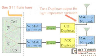
AWT6221 the development of reference design starting in the power amplifier to further coupling with the duplex S parameter measurements. In this measurement, the zero-ohm resistors are used to shorten the circuit board matching components (Figure 3).
Dual-band CDMA-EVDO and WCDMA-HSDPA Power Amplifiers

Figure 3. Schematic Diagram AWT6221RDA

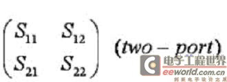
Describe the N-port S parameters for each one-port network response of the voltage signal. The first number of the subscript refers to the response to mouth, while the second figure refers to the case mouth. S21 refers to the signal side, therefore a result of two reactions in the mouth. S parameters of an equal number of rows and columns from the matrix port. S matrix along the diagonal of the parameters are known as the reflection coefficient, diagonal S parameters are referred to as transmission coefficients, because they only occur in a single port. S matrix of two-port network in the table below:Dual-band CDMA-EVDO and WCDMA-HSDPA Power Amplifiers

Reflection coefficient (S11) for band 2 and band 5 the frequency range of RF paths to test. Power amplifier at the output of the circuit is not in line with the formation of a series of impedance changes, the results displayed in the Smith form (Figure 4, Figure 5).

Dual-band CDMA-EVDO and WCDMA-HSDPA Power AmplifiersFigure 4. Cell Band: PA output to Antenna

Dual-band CDMA-EVDO and WCDMA-HSDPA Power AmplifiersFigure 5. PCS Band: PA output to Antenna

For any power amplifier, the output impedance have a major impact in the operation, and a strong influence on the transfer to the antenna, linear (ACLR) and operational efficiency of power. ANADIGICS power amplifiers as the vendor can help engineers to do a good job balancing the load-pull of information. Optimum output impedance will be other characteristics of RF chain, the influence of components such as diplexers and switches are not always 50Ω. Variation frequency band characteristics of the advantages of duplex and operating temperature, in well-developed WCDMA RF design, particularly challenging.

Electronics Now

Your Ad Here
User Agreement

The creator of THIS PAGE or the ISP(s) hosting any content on this site take NO responsibility for the way you use the information provided on this site. These circuits here are for educational purposes only and SHOULD BE VIEWED ONLY. If you download any files to view them, you are agreeing to delete them within a 24 hour period. If you are affiliated with any government, or ANTI-Piracy group or any other related group or were formally a worker of one you CANNOT enter this web site, cannot access any of its files and you cannot view any of the HTML files. All the objects on this site are PRIVATE property and are meant for previewing only. If you enter this site without following these agreements you are not agreeing to these terms and you are violating code 431.322.12 of the Internet Privacy Act signed by Bill Clinton in 1995 and that means that you CANNOT threaten our ISP(s) or any person(s) or company storing these files, cannot prosecute any person(s) affiliated with this page which includes family, friends or individuals who run or enter this web site. IF YOU DO NOT AGREE TO THESE TERMS THEN LEAVE.

Disclaimer

All files are found using legitimate search engine techniques. This site does not and will not condone hacking into sites to create the links it list. We will and do assume that all links found on the search engines we use are obtained in a legal manner and the webmasters are aware of the links listed on the search engines. If you find a URL that belongs to you, and you did not realize that it was "open to the public", please use the report button to notify the blogmaster of your request to remove it. This is not an invitation for webblog haters to spam with requests to remove content they feel that is objectionable and or unacceptable. Proof of URL ownership is required.
NOTICE: This Blog Has Already Been Reviewed And Accepted By Blogger.com

© 2013. Another Electronics Circuit Schematics. Powered by Blogger.
 

blogger templates | Make Money Online