by Ralph Calabria 
(If you would like to have your DIY project published in Secrets, please E-Mail Ralph Calabria at rc@sdinfo.com.)
Introduction
Definition (Webster's Ninth New Collegiate Dictionary):
titan \'tit-en\ n [Gr] 1: cap : any of a family of giants born of Uranus and Gaea and ruling the earth until overthrown by the Olympian gods. 2: one that is gigantic in size or power: one that stands out for greatness of achievement.
If definition #2 is true, the Titan subwoofer should be a real winner. Let's see if the Titan holds up to its name, or is it merely a Greek myth?!
Now I know a lot of you are saying, "Oh no, not another subwoofer project! Can't we have a little variety?" OK, I admit it. BUT, this project has some major differences in its design compared to previous ones. The most important difference is that it is a powered sub, which means it has its own amplification system and active crossover. Besides, one of the biggest and most noticeable improvements one can make to an existing setup is adding a good powered subwoofer. Since this sub can be purchased as a kit, this article is intended to do double duty as a DIY project and a kit review. If you haven't gotten the speaker building bug yet, or you're still contemplating but haven't taken "the plunge", this just may be the project to get your feet wet. Building this puppy is super easy and fun!
Who is Audio Concepts (ACI)? There are probably some folks out there who have never heard of them. That may be because they are a company that deals directly with the consumer. No middle man. No distributor. No sales person. Their advertising campaigns are not as "in-your-face" as some of the larger companies. "Dealing Direct" has become vogue of late, but ACI has been doing it for over 20 years. Founded by Dr. Mike Dzurko, the company has evolved from a one-man show to a very successful business that works out of a renovated nineteenth century church. The company's forte is providing high quality loudspeaker systems at a reasonable price. By avoiding the layers of profit-takers, ACI can pass some of the savings to their consumers.
Design considerations
I was looking for a sub that pretty much did it all: response to 20 - 25 Hz -3db with substantial output, flexibility to ensure a seamless blend between the sub and my existing main speakers, an attractive looking design that could double as speaker stands (should I decide to get stereo subs), all in an enclosure that wouldn't take up half the free space in my home theater room. I don't think that's asking too much! Do you?
I first looked into designing a sub from scratch. Among the many DIY drivers I considered, the ones I found on ACI's home page caught my eye, in particular the ACI 12E and the ACI DV12 (both 12" drivers). They offer several alignments for their drivers in both sealed and vented configurations. I checked them out with my MacSpeakerz box design program and confirmed ACI's alignments. However, to get even 25 Hz flat out of these drivers, I would have to build a cabinet with about 5 ft3
internal volume. That translates into one massive, heavy box! Considering these designs, I would still have to come up with an active crossover to provide the flexibility I wanted, plus a power amplifier to driver the speaker. Although my home theater room can use a couple of new end tables, I decided that these monsters would just be too big for what I envisioned.
I've known about the Titan for a couple of years now, and I was aware of the good reviews the Titan (and other ACI products) have received over the years. I decided to look at the Titan a little more closely to see if it was a match for my design criteria. As fate would have it, the Titan was just what I was looking for in terms of power, flexibility, size, extension, and output.
The Titan comes in two forms. There's the just-plug-it-in-and-off-you-go form, which sells for $799, and there's the Do-It-Yourself form, which is a kit that comes with just about everything you need except the cabinet. The kit sells for $529, but it is currently priced (for a while) at $499 (including free shipping). If budget is your concern, and you are handy with tools, you won't find a better deal than this, considering it has a 12" driver and 250 watt amplifier.
After speaking with my friend Leo, and asking him if we could cut some MDF at his dad's house, he asked me what I was building this time. When I told him it was a powered sub, he wanted in on the action. So, I offered to help him build one. I did have an ulterior motive, however. I was looking to check out stereo Titans. After getting his OK to borrow his Titan for the evaluation when it was finished, we were set to go.
The Titan design
The Titan was designed to operate in a relatively small sealed cabinet (1.9 ft3 internal volume; Q = 0.6). At this box volume and a standard closed-box Q of 0.707, the ACI 12E will stay flat to about 40 Hz, then drop off at 12 db/octave below 40 Hz (meaning -12 dB at 20 Hz). So how does a speaker like the 12E, designed to go flat to 40 Hz at this box size, extend its useful range to about 20 Hz? This is done by inserting an electronic circuit before the amplification of the signal that boosts the frequencies at the point where they start dropping off (at 12 dB/octave). This is called equalization (EQ). To accomplish this, particularly at these low frequencies, takes quite a bit of amplification ability. Not just any system can be EQ'd. The driver also has to be able to handle everything that's being thrown at it. A motion accelerometer sensor is sometimes added to protect the driver from distorting or blowing up. This type of approach, commonly known as active-servo control, performs as a feedback controller by limiting the output the driver sees as driver limitations are approached. Several powered subwoofers on the market use this technology. For the Titan, the woofer is put in the output loop of the amplifier. This is how ACI gets the Q of 0.6 and extends the response to about 20 Hz. The Titan uses a high-pass crossover filter that is controlled at 20 Hz with an 18 db/octave slope. When the driver/amp limitations are approached, the frequency of the filter increases. The downside is the Titan won't be permitted to play tones much below 20 Hz at any appreciable volume. The nice thing about the Titan design is that the upper frequency limit does not change, and constant output is maintained. For example, if you have the Titan's crossover set at 70 Hz, and the frequency limiter is activated, frequencies that are between the set limiter and 70 Hz are not affected with regard to output. This approach maintains the seamless blend (crossover point) you've set for your mains and sub.
The Titan comes with a 250 watt rms amp specified at 0.1% THD. The amp has a massive toroidal transformer, bipolar output devices, and computer grade power supply capacitors with selected film caps in the signal path. 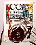 A temperature switch monitors the output devices of the amp. If the amp overheats, the system shuts down to protect the circuits. Once the heat sinks cool, power is restored.
Aside from the current-sensing feedback circuitry, the Titan comes with an active crossover that allows you to select any low pass crossover frequency from 50 Hz to 180 Hz. The filter starts at 12 dB/octave and increases to 24 dB/octave. There is also a phase switch that allows you to set the sub at 0° or 180°. Most manufacturers provide speaker-level inputs and outputs on their subs so the amplified signal coming from the receiver/amp is sent to the speaker-level inputs of the sub, then routed through a high-pass filter, and on to the satellite speakers by way of the speaker-level outputs on the sub. The Titan does NOT have speaker-level inputs/outputs. It does come with three speaker-level adapters. These adapters essentially convert a speaker-level output coming from a receiver to a line level output. This line level output is then hooked up to one of the three Titan line-level inputs. If you have a line-level sub output on your receiver/preamp, you don't need to use the adapters. If you're looking to limit the frequencies your satellite speakers see, ACI sells a high-pass filter (~85-90 Hz; 1st order slope). For a detailed description (including photos) of the many ways to hook up a Titan to your system, check out ACI's home page at http://www.audioc.com/diy/kits/titank.htm.
The Titan kit
The following hardware is included with the Titan kit:
1 - 12" long-throw polypropylene woofer (ACI 12E)
1 - 250 watt rms amplifier module with variable active crossover
3 - speaker-level to line-level adapters
2 - speaker terminal connectors
Closed-cell adhesive-backed foam
Acoustical polyester stuffing
Instruction/owner's manual
The following hardware is NOT included with the Titan kit:
Wood to build the cabinet
Cabinet finishing materials
Screws to secure the woofer and amplifier
Speaker spikes (points)
The kit came tightly packaged in one box. The amplifier/crossover module comes completely assembled, so there's no need to solder anything. The manual includes some frequently-asked questions (and their answers) regarding building DIY speaker projects as well as some other useful information regarding setup and placement of the sub. The actual assembly-process part of the manual was a little thin. Although most of the diagrams were just fine, some of the cabinet diagrams were a bit confusing. I thought there could have been additional assembly instructions to better help the newbie on the block. The cabinet diagram also states that the circle cutout measurements for the driver and cabinet base top are a radius cut, when it should be stated as a diameter measurement. Anyone with some common sense, however, could figure out that an 11 1/4" radius circle (implying 22 1/2" diameter) won't fit in a cabinet that's 13 1/2" wide! The descriptions of the braces were not fully described as well. For example, the internal brace diagram shows a brace 2" wide for all sides. This is fine for the upper brace. However, there is no indication that the lower brace should be cut to accommodate the amplifier hole in the back. Again, common sense prevails here, and the drawing of the cabinet with a portion of the wall cut out for internal display purposes DOES show the brace cut, but you really have to look. A quick and simple update of the drawings would probably eliminate a lot of phone calls to ACI for clarification. I had no problem figuring out the internal dimensions from the plans, but perhaps it would be helpful if there was a list of board dimensions, a quantity of each size, and what the boards are used for, something on the order of the diagrams I've included for my enclosure. This would make the construction process a little less confusing. Everything I've mentioned here never presented a problem in the construction process. Most of the suggestions I've made are based on how I personally prefer cabinet plans to be laid out. During the initial part of the design layout, I had some questions about the plans, and Mike and Joe at ACI were very helpful and receptive in this area.
The cabinet
ACI cabinet plans
The Titan cabinet has an internal volume of approximately 1.9 ft3 and measures externally 13.5"W x 14.5"D x 26.5"H. The height includes the cabinet base, which is screwed onto the bottom of the cabinet. The driver is configured in a down-firing position. The design incorporates four braces; two "mini" braces and two square cutout braces. All walls and braces are constructed of 0.75" MDF. The cabinet base is constructed of 1" MDF, and is assembled separately from the cabinet. There are 4 - 1" diameter x 1 3/8" H dowels that are sandwiched between the top and bottom of the cabinet base. For a more detailed description of the cabinet drawings, go to ACI's website listed above.
Modified cabinet plans
Here are the cabinet plans I used for my sub:
The overall height of the Titan cabinet was a little too tall to double for a speaker stand. My main speakers need to be at a height of approximately 22" - 24" off the floor in order for the tweeter to be at ear level when seated in the primary listening position. In order to bring the overall height of the cabinet down a bit, I had to change the dimensions. When it comes to building speaker cabinets, I've always lived the philosophy of "build it as strong as you can without needing more than three people to move it". Considering I would potentially use the sub(s) as a speaker stand, I didn't want my mains vibrating off the sub. I decided to use 1" MDF for the walls, braces, and cabinet base. Using 1" MDF increases the stiffness of the cabinet by a factor of 2.4. (Stiffness is proportional to the wall thickness cubed. A 1" wall is 1.3333 times thicker than a 0.75" wall. So, 1.33 X 1.33 X 1.33 = 2.4.) I also modified the bracing somewhat. The two top braces where changed from 2" wide to 1.5" wide. Because the cabinet was made shorter, everything inside was compressed. So, in order to leave at least 3" between the shelf brace and the top braces, I shortened them by 1/2". The middle brace was changed to a shelf brace (see cabinet drawing for details). The bottom brace was left unchanged. However, an additional 1 1/2" wide brace was added which sits on top of the bottom brace across the width of the cabinet. This was an afterthought. When the cabinet was assembled with the exception of the front panel, I whipped out my high-accuracy cabinet-stiffness testing apparatus, a.k.a., the knuckle of my right middle finger. Striking the knuckle at various intercepts on the cabinet, and using a constant linear velocity of 15.24 cm/second equidistant from the cabinet, I determined that the lower brace needed some "beefing up". Because the lower brace is cut to accommodate the amp, a shelf brace was not possible. So, I guess you can call it a half-shelf brace. There's a big difference in the "stiffness test" at the middle shelf brace compared to the lower brace. The "pitch" of the cabinet is much higher at the shelf brace (higher is better). Adding the extra bracing helped raise the pitch of the cabinet at the lower brace.
The original plans call for making the cabinet base as a separate unit. Although the bottom of the cabinet base and the dowels are separate from the main cabinet in my design, I decided to make the top of the cabinet base a "permanent fixture" of the main cabinet. Why? Gluing and screwing the top of the cabinet base to the main cabinet strengthens the baffle. Also, by making the top of the cabinet base part of the cabinet, I got the cosmetic look I was going for in a veneered piece rather than a painted piece. Did I HAVE to make all these changes? Of course not. The original cabinet design is more than adequate (and attractive too). However, if you can, and it if works for your design goals, why not?! This decision was driven mostly by cosmetics. (NOTE: Just keep in mind that if you change the dimensions of the original plans, make sure the internal volume stays at 1.9 ft3 ± 5%, after accounting for bracing). The overall sound of the sub shouldn't change. Making this alteration will, however, make it more difficult, but not impossible, to remove the driver. The driver is 12 1/4" in diameter, and so is the hole in the upper cabinet base. I don't plan on removing the driver very often (hopefully never!), so I didn't consider this a major pain.
Assembling the cabinet
After building my Audax A652s (DIY #1), I 'd say that building this sub was a cake walk. I could easily recommend this kit to anyone who has never built a speaker project before, provided they have some woodworking know how (or know someone who does), a lot of common sense (or know someone who does), and access to some power tools. Many of the techniques I used in making the A652s were also used in making the Titan.
After cutting all the panels with a table saw, I used a jigsaw to cut the holes for the amp and the braces. I used a router with a circle cutting jig to cut out the holes for the driver and the top of the cabinet base. I assembled the back and the two sides first, using the glue-and-screw technique. I would recommend getting a couple of 90° clamps for this part of the assembly. The pieces are first dry fitted and aligned using these clamps, then one piece is raised up to apply the glue, the boards are clamped together again and then screwed using #6 1 5/8" drywall screws (don't forget to coutersink). Once the pieces are screwed, the clamps may be removed and used for the next pieces to be assembled. These braces really are worth their weight in chocolate. It makes this part of the construction a one-person job.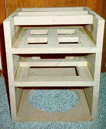
Once the back and sides were assembled, I installed all the braces and the baffle. To keep everything in place while screwing in the pieces, I used three Eagle Bar clamps with a 30" extension; one to pull the sides in and two to pull the brace down into the back of the cabinet. These clamps did a great job at keeping everything snug and in place while I drilled the pilot holes for the screws. The small 1.5" braces were held in place by two bar clamps until glued and screwed in place. Keep in mind that in the cabinet diagram, the positioning of the braces is determined by the FREE-SPACE distance from the bottom of the cabinet. If you want to measure from the bottom of the cabinet, add 1", which is essentially the thickness of the baffle. The shelf brace should start approximately 1/2 inch above the amp cutout.
I then installed the top and the cabinet base top. I didn't need to flush mount the driver in this case. No one's going to see the down-firing driver, so cosmetically it's not a concern. I sealed all the outside joints of the cabinet with Silicone II, then put the front on and sealed that as well. Once the cabinet was assembled, I filled all the countersink holes with wood filler. When the wood filler was dry, I sanded the entire cabinet using a random orbital sander. I sanded all the butt ends until they were flush with each other. I routed the two front edges of the enclosure using a router and a 1/2" roundover bit. The bottom of the cabinet was then spray painted using a semi-flat black enamel. 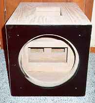
Cabinet finishing
Cabinet finishing is always up to the end-user. There are many ways to finish a cabinet. Painting, rugging (there's just no accounting for taste!), veneering, and laminating are just a few of the more common finishing processes used. I love the look of real wood. Since I can't make my cabinets out of real hardwood (there are many reasons why you shouldn't build your speaker cabinets out of solid hardwood), the next best thing is to use real hardwood veneer to cover the MDF cabinet. I chose a 10 mil paper-backed red oak veneer to match my A652s. There are a few ways to apply veneer to MDF. The most common are using varying types of contact cement, wood glue using clamps or vacuum presses, hide glue, and dried wood glue. I decided to use what worked for me on the last project, the dried wood glue and hot iron technique. The last time I tried this technique, I applied the glue to both the cabinet and the veneer in somewhat liberal proportions. The glue, being a water-based product, took on the order of several hours to dry. This time I applied a thinner coat of glue to both the veneer and the substrate. As the glue dried, I checked for any areas that weren't shiny (an indication that the glue soaked into the MDF/veneer). I applied another thin coat of glue, not waiting for the first coat to dry. Even though I used two thin coats of glue, it only took about 1 1/2 hours for all the water to evaporate. It's important to make sure that all the water is gone. If water is still present in the glue, it will boil when the iron is applied, and the veneer will bubble. To accelerate the drying process, I applied the glue in a warm, dry room and used a space heater to get it nice and toasty. Working with the dried glue immediately after the water has evaporated really helped melt the glue more easily and enabled the bond to take place quickly. This resulted in no bubbling or scorching of the veneer. For a detailed description of this technique, check out the Audax A652 project (DIY #1) at http://www.sdinfo.com/volume_3_3/v3n3d.html. As each piece was bonded, I used a veneer trimming bit on my router to shave the excess off the edges. Preparation of the veneer for staining was done as in DIY#1. 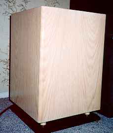
The stain was the same pickling oak stain in order to match my mains, and the topcoat was semi-gloss polyurethane. For a detailed description of the finishing procedure, once again I refer you to DIY #1 at the above URL.
Installing the driver, amp, and stuffing
The last chapter in the assembly process is putting in the stuffing (damping material), attaching the wires from the amp to the speaker, and installing the speaker and amp module. Before applying the stuffing, I vacuumed out any sawdust that had fallen in, then used a spray adhesive to keep the stuffing in place in the cabinet. The stuffing comes in a sheet that is about 2' x 4' x 3/4". I "poofed" it up and made sure the stuffing material was not too close to the driver. I allowed some space for the driver to breathe and the cone to move freely. The extra brace piece on the lower brace helped keep the stuffing from falling down onto the driver. (NOTE: If you use spray adhesive, wait until the fumes from the spray adhesive have completely evaporated before moving on.)
I then applied the foam gasket material to both the driver and amp. The kit does not come with the hardware to install the amp and driver, so you're on your own here. (I can see not including screws for the driver, as some DIYers prefer to use T-nuts or some other method. The amp, however, has six holes used to screw it into the cabinet. I would like to have seen hardware provided here to eliminate the guess work with regard to the length, head size, etc.) I installed the amp first, then the driver. For the amp I used #6 3/4" black pan head particle board screws, and for the driver I used 1 1/2" black pan head screws. The driver screws were a wee bit long for the job, but the head on them was a perfect fit for the driver (and I had them in surplus :-). The kit comes with speaker terminal clips that make the amp-to-speaker connections easier. This requires crimping one end to the amp wire and crimping the other end to the speaker terminal, red to positive and black to negative. No soldering is necessary.
Cabinet Base
As I described earlier, the top of the cabinet base was integrated with the main cabinet. The bottom of the cabinet base was routed on all four sides using a 3/8" beading bit to make it look like molding edge. The dowels were cut 1 3/8" long using a miter saw. I used a slightly fatter dowel (1 1/4") than the original design because my cabinet is wider and heavier. The dowels were stained with the pickling oak stain and top coated with semi-gloss polyurethane.
A hole was drilled through the center of the dowel. The dowels were then positioned 1 1/2" from each adjacent side of the cabinet base bottom, and a hole was drilled into the cabinet base bottom through the hole in the dowel. The hole was made just large enough to allow a #10 4" drywall screw to pass through with a little resistance. I aligned the cabinet base bottom with the main cabinet bottom and drilled a pilot hole in the main cabinet. The top and bottom of the cabinet base were then spray painted gloss black. The holes in the cabinet base bottom, dowels and cabinet were aligned, and the drywall screws were used to attach the base.
After everything was together, I installed a set of speaker spikes on the bottom of the base. I used a set of ACI extra points, which are not included with the kit.
It's break-in time!
Audio Concept really stresses the need to break in the Titan for at least 40-60 hours. That's a lot of bass notes! They claim it is necessary to stretch out the driver surround. Before doing any serious listening, I played some bass-kicking CDs. I tried to do most of the break in when everyone was fast asleep or when no one was at home (when trying to break in a wall-shaker like this sub, you don't WANT to be home when pictures start falling all around you)! I listened to the Titan for a while with no break in time, and then again at various stages of the break in. The Titan behaved like a fine scotch, getting better with age. It also got louder with time during the break in (just ask my wife at 3:00 a.m.) Based on my experience, I would suggest a minimum of 40 hours before really trying to evaluate the performance of this sub. You'll be duly rewarded!
Days of thunder
I first went about finding the best place in my room to plop down the sub (Position #1 described below). After finding the right crossover point, I was able to provide a seamless blend between my mains and the Titan. The Titan was primarily designed for music reproduction, and I'd say up front that it did an excellent job at this. The first thing that jumped out about this sub was the tightness of the bass. With a system Q of 0.6 in a sealed enclosure, this was not surprising. The sub also had excellent transient response. This was made apparent when listening to the timpani in "Farefare for the Common Man" (Aaron Copland - Telarc). The Titan's sealed enclosure provided very controlled bass. No matter how loudly I played the Titan, there was no audible sign of distortion. This was expected because of the Titan's feedback loop controller, but all the same, its electronic devices worked quite well. After playing track after track of bass-enriched CDs, the Titan continued to impress me with its solid, clean, tight bass, all at ample output. I can't stress enough how musical this sub sounds.
So, what about movies? It's hard to find a sub that can deliver both a satisfying music AND movie experience. There's no question as to the Titan delivering the goods for musical reproduction. However, a sub has to produce a fair amount of tactile effects to be convincing in movie soundtrack reproduction. The way my room is situated, some compromises needed to be addressed. In the position where the Titan exhibited the smoothest response and produced "delocalized" bass (Position #1; between my mains), the sub's tactile effect was reduced. In the position where the greatest tactile effect was produced (Position #2; off to the right of my right main, close to my couch), there was definite localization of the bass, which was very distracting, particularly when watching movies. I found this phenomenon to be attributed to the floor in my home theater room and not the subwoofer. My floor is concrete, covered with hardwood planks, and then by carpet. Very hard, and very dead! Although I couldn't really feel the bass in position #1, the walls vibrated enough to rattle clocks and pictures. However, there was a totally different experience going on upstairs. My living room floor directly above my home theater room almost reached its resonance frequency! My daughter, watching TV upstairs, almost lost her glass of milk, which she had placed on the floor. In position #2, I could feel the bass more (my body vibrating) because the sub was close to my couch, and the vibrations were transferred to me through the couch.
I selected some bass-intensive scenes from the "Star Wars Trilogy Special Edition", Disney's "Aladdin", "The Lost World: Jurassic Park", "The Fifth Element", "Contact", and "Twister" to put the Titan to the movie test. Although the Titan was designed to be more of a musical sub, it did a fine job reproducing movie special effects such as explosions, rocket engines, claps of thunder, and associated rumbles. The Titan didn't flinch, no matter how loudly I played it. My ears gave out well before the Titan did. However, the Titan will only play as loudly as the limit controller will allow, starting by slowly cutting off the lowest octave first and working its way up the frequency scale. As I continually cranked it up, I sensed no discontinuity in the balance of my system, indicating that the output of the upper frequencies close to the crossover point of the sub and mains was not interrupted.
Associated equipment for this evaluation included:
B&K AVP2000 preamp
B&K AV5000 power amp
Pioneer CLD-D703 combi player (modified for AC-3)
Marantz DP-870 Dolby Digital Processor
DIY Audax A652 mains
Paradigm CC-300 center speaker
Paradigm ADP-150 surrounds
Audioquest Quartz and Indigo cables
Are two thumpers REALLY better than one?
As I mentioned before, my friend Leo was nice enough to lend me his Titan for the stereo sub evaluation. For this test, I replaced my speaker stands with the subs and put my mains on top.  I separated the mains from the subs using four high-density foam pads at each corner of the mains.
Using two subs will give you the flexibility of keeping the subs' crossover point slightly higher (if your setup calls for it), as bass delocalization is less of a concern. Using two subs also increases output by about 6 dB (but there can be cancellation at some frequencies, so placement is critical).
Using two Titans produced a smoother, more balanced in-room response when I compared the same music tracks using a single sub. The overall sound improvement was very noticeable on movie playback as well. As I mentioned before, my room effects contributed to or took away from the tactile effect of the sub. However, with two subs, the overall effect with movies was astounding, with great balanced, centralized sound, AND phenomenal special effects. Two subs with this much output extending down this low is almost suicidal!
Cost estimate
Here is a breakdown of the overall cost of the project. I had a lot of the hardware materials left over from my last project. I didn't include them in the price. However, I did give a unit cost so these may be added should one not have these materials around. Since materials cost varies from region to region, your cost may differ somewhat.
TITAN KIT: ACI
1- ACI 12E 12" polypropylene cone driver - - -
1- 250 watt amplifier module - - -
Acoustical polyester fill - - -
Foam gasket material - - -
3- Speaker level adapters - - -
Kit Cost: $499.00
Building Materials:
| Material | How Much | Price | Source |
| 1" Medium Density Fiberboard | 25 ft2 at $0.96/ft2 | $24.00 | Lumber Yard |
| 1 1/4" Hardwood Dowels | 0.5 Foot at $1.00/Foot | $0.50 | Home Depot |
| Carpenter's Wood Glue | 1 Bottle at $5.49/Bottle | $5.49 | Home Depot |
| Silicone II Sealant | 1 Tube at $2.97/Tube | $2.79 | Home Depot |
| #6 1 5/8" Drywall Screws | Handful at $2.30/Pound | $2.30 | Home Depot |
| Black Anodized Screws | 14 at $2.50 for 50 | $2.50 | Home Depot |
| Red Oak Veneer (paper backed) | 16 Feet2 at $1.30 Foot2 | $20.80 | Lumber Yard |
| Pickling Stain | 1 Quart MinWax at $5.69/Quart | $5.69 | Home Depot |
| Gloss Polyurethane | 1 Quart MinWax at $8.49/Quart | $8.49 | Home Depot |
| Speaker Spikes | 1 Set of 4 at $15.00/Set ACI | $15.00 | ACI |
| Black Spray Paint | 2 Cans at $1.59/Can Krylon | $3.18 | Home Depot |
| Wood Filler | 1 Can at $4.89/Can | $4.89 | Home Depot |
Materials Cost: $71.42 (estimated from using only part of the tubes and bottles)
Grand Total: $570.42
For the most part, people like to save money. By doing it yourself, you're doing just that. The total cost of this project was about $570. Buying a Titan pre-assembled would cost $799. So, you're saving about $230 by building your own cabinet. You get the added advantage of building it to suit your needs (size, strength, shape, cosmetics, etc.), and you get the satisfaction of knowing you did it yourself. Although building this cabinet was pretty easy, it's also important to know that using the right tools and techniques will help your chances to succeed. Should you decide to build the cabinet yourself, and find that it's not turning out quite the way you expected, fear not. ACI sells the Titan cabinet as a stand-alone item. All you would need to do is install the hardware. You won't save any money, but your investment in the kit is not lost.
Final remarks
If you're looking for a sub that will reproduce audio soundtracks with tight, detailed, natural bass, you may have to search long and hard for a better sub than the Titan. Can you buy (make) a sub that will produce higher output levels and extend lower than the Titan? Yes. But I think the question you should be asking yourself is do I NEED a sub that will produce higher output levels and extend lower than the Titan? That answer really depends on your requirements (desires) and the amount of cash you have burning a hole in your pocket. After listening to the Titan for a while, I have to admit that even at $799 straight from the factory, the Titan is quite a deal. This attractive looking sub (which also makes for a very attractive speaker stand) certainly performs and looks like a more expensive component. I have heard subs costing twice the price, and looking half as nice, and the Titan stays very competitive. If you've got the funds to support two Titans, even better! Your subwoofer needs will be satisfied for many years to come, all at a mere DIY price of about a kilobuck. I do have one problem, however. How am I going to tell Leo that he's not getting his Titan back!
Factory direct, the Titan is available in three finishes: clear lacquer oak, clear lacquer cherry, and black stained oak. Other special-order finishes are available by request.
The Titan certainly lives up to its name. Thank you, Mr. Webster, for summing it all up for us!
Special limited-time offer
ACI will be holding a special limited-time offer to readers of Secrets of Home Theater and High Fidelity. If you order the Titan kit and mention this Secrets article, ACI will include a set of Extra Points speaker spikes at no additional charge.
Acknowledgements
I'd like to thank Leo and his dad for helping me cut the wood on their table saw, and to Leo for lending me his Titan for the stereo sub evaluation. Thanks also go out to Mike Dzurko for all his help during the Q&A (pre-construction) portion of this project and for making such a nice powered subwoofer kit available to DIYers.
Ralph Calabria
Tags:
Schematics, Electronic Circuit, Mosfet Amplifier, Audio Amplifier, Active Filter, Basic Knowledge, Basic soldering, Car Audio, Datasheet, Design, Make PCB, Modding, Power Amplifier, Power RF, Pre Amplifier, Power Supply, Loudspeaker


")


")