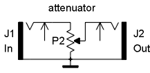
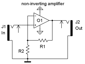
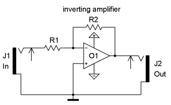
Simple attenuator This is a simple passive attenuator (i.e. no power supply required). J1 is the input socket, J2 the output socket. A typical value for P2 is 10k...100k. A linear or logarithmic type can be used for P2 (logarithmic especially for audio applications as the loudness characteristics of the human ear is approx. logarithmic). Simple lowpass This is a simple passive lowpass with 6dB/octave slope. A non-inverting amplifier can be added at the output (and even at the input) to make the circuit independent of input/output impedance (i.e. the "loads" connected to J1 resp. J2). Replacing of R1 by a vactrol leads to simple voltage controlled lowpass filter. Replacing R1 by a potentiometer leads to a simple manually controlled lowpass filter Frequency of the lowpass: f = 1/(2 * Pi * R1 * C1) with Pi = 3.14 Simple highpass This is a simple passive highpass with 6dB/octave slope. A non-inverting amplifier can be added at the output (and even at the input) to make the circuit independent of input/output impedance (i.e. the "loads" connected to J1 resp. J2). Replacing of R1 by a vactrol leads to simple voltage controlled highpass filter. Replacing R1 by a potentiometer leads to a simple manually controlled highpass filter Frequency of the highpass: f = 1/(2 * Pi * R1 * C1) with Pi = 3.14 Non-inverting amplifier This is a simple non-inverting amplifier: The term "non inverting" means that the polarity of input and output signal are the same. In other words: a positive input signal applied to J1 will cause a positive output signal at J2 and a negative input signal applied to J1 will cause a negative output signal at J2. The amplification of this circuit is 1 + R1/R2. If R1 or R2 is replaced by a potentiometer the amplification can be adjusted. If e.g. R1 in the last example is replaced by a 100k potentiometer the amplification is adjustable in the range 1...11. This circuit can be used to built an simple amplifier if the desired audio or CV signal is too small for a certain application. Attention ! The minimum amplification of this circuit is 1 (no real attenuation possible provided that no external attenuator is used). Inverting amplifier This is a simple inverting amplifier: The term "inverting" means that the polarity of input and output signal are opposite. In other words: a positive input signal applied to J1 will cause a negative output signal at J2 and a negative input signal applied to J1 will cause a positive output signal at J2. The amplification of this circuit is - R2/R1 (" - " indicates the opposite polarity of input and output) The minimum amplification of this circuit is zero (if R2 = 0). To obtain a non-inverted output another inverting amplifier with amplification - 1 has to be used. The inverting amplifier can be extended by adding more input sockets (J1) and corresponding input resistors (R1). The right terminals of all input resistors are connected to the inverting input (-) of the operational amplifier O1. The relation between the corresponding input resistor R1 and R2 (the same for all inputs) defines the sensitivity of the input in question. If all resistors have the same value (e.g. 100 kOhm) the amplification is "1" for all inputs. Lowering R1 (e.g. 47k or 22k) increases the sensitivity of the input in question. Increasing R2 (e.g. 220k or 1M) increases the amplification resp. sensitivity for all inputs simultaneously. The first circuit example (chapter 3: "CV mixer with offset function") shows a typical application of inverting amplifiers with several inputs.

Example: R1 = 47kOhm, C1 = 10nF -> f ~ 340 Hz 
Example: R1 = 10k, C1 = 2,2n -> f ~ 7.2 kHz 
Example 1: R1 = 0 Ohm (connection), R2 omitted -> A = 1
Example 2: R1 = 47k, R2 = 47k -> A = 2
Example 3: R1 = 100k, R2 = 10k -> A = 11 
Example 1: R1 = R2 = 47k -> A = - 1
Example 2: R1 = 10k, R2 = 100k -> A = - 10
If R2 is replaced by a potentiometer the amplification can be adjusted. If e.g. R2 in the last example is replaced by a 100k potentiometer the amplification is adjustable in the range 0...-10. This circuit can be used to built an simple (inverting !) amplifier if the desired audio or CV signal is too small for a certain application.
The minus terminal of the operational amplifier is often called "virtual GND" in this circuit as the voltage measured at this point is very close to GND within a few millivolts - independent of the incoming voltages!

Search... ELectronics :
Basic circuits
Electronics Now
-
1. Power Amplifier Basic Circuit Characteristics Complementary symmetric OTL amplifier basic circuit as shown in Figure 1. Where: C1 for the...
-
The famous SGS-THOMSON ST Microelectronics has introduced a Hi-Fi DMOS high-power amplifier circuit TDA7294, its sound great taste bile, whi...
-
The fact that we need a subwoofer means that something is missing in the performance of the main speakers. This is not surprising, since the...
-
You have purchased construction quality Hi-Fi amplifier operating in class AB. Thanks to its small size, protected against short circuit on ...
-
Figure principle of good restructuring. The amp features: Changed the top, replacing self-made Indian plate of trouble. DC servo output DC-...
Categories
The creator of THIS PAGE or the ISP(s) hosting any content on this site take NO responsibility for the way you use the information provided on this site. These circuits here are for educational purposes only and SHOULD BE VIEWED ONLY. If you download any files to view them, you are agreeing to delete them within a 24 hour period. If you are affiliated with any government, or ANTI-Piracy group or any other related group or were formally a worker of one you CANNOT enter this web site, cannot access any of its files and you cannot view any of the HTML files. All the objects on this site are PRIVATE property and are meant for previewing only. If you enter this site without following these agreements you are not agreeing to these terms and you are violating code 431.322.12 of the Internet Privacy Act signed by Bill Clinton in 1995 and that means that you CANNOT threaten our ISP(s) or any person(s) or company storing these files, cannot prosecute any person(s) affiliated with this page which includes family, friends or individuals who run or enter this web site. IF YOU DO NOT AGREE TO THESE TERMS THEN LEAVE.
All files are found using legitimate search engine techniques. This site does not and will not condone hacking into sites to create the links it list. We will and do assume that all links found on the search engines we use are obtained in a legal manner and the webmasters are aware of the links listed on the search engines. If you find a URL that belongs to you, and you did not realize that it was "open to the public", please use the report button to notify the blogmaster of your request to remove it. This is not an invitation for webblog haters to spam with requests to remove content they feel that is objectionable and or unacceptable. Proof of URL ownership is required.
NOTICE: This Blog Has Already Been Reviewed And Accepted By Blogger.com

This work is licensed under a Creative Commons Attribution-NonCommercial-NoDerivs 3.0 Unported License.


0 comments:
Post a Comment