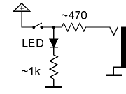
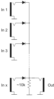
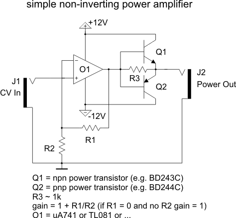
Mixer with optional offset function and inverted/non-inverted outputs Inputs J1 ... J3 are standard inputs. At J5 the inverting sum of all inputs is available. J6 outputs the non-inverting sum. P5 allows an additional attenuation of the complete signal (affects only J6). Typical values for the parts used: The value of R8 defines the offset range (about 0...+6V for R8=33k, a lower value of R8 will increase the offset range and vice versa). Matrix Mixer Matrix Mixer The CV mixer described above can be expanded to a so-called matrix mixer. This circuit has several inputs available (three in the example circuit) that can be mixed to different outputs (three in the example circuit) with adjustable levels. At each point of the matrix a potentiometer is available that defines the level for the matrix junction in question. The circuit can be used for CV or audio applications. The number of inputs and outputs can be increased to the desired value of columns and rows. For each of the outputs the two OpAmp circuit with the corresponding output socket is required. For each input another socket and the corresponding quantity of potentiometers and resistors is required. Typical values for the parts used: To obtain a higher or smaller overall amplification the feedback resistor of the first (left) OpAmp of each output circuits has to be adjusted (as described above). It is recommended to use a separate pcb for the output circuits. The input sockets and matrix potentiometers/ resistors can be wired by hand very easily. Manual Gate Manual Gate The left picture shows the basic circuit of a manual gate. The 470 Ohm resistor serves as a short circuit protector. Without this resistor the +12V supply would be shorted to GND if a patch cable is inserted to the socket while the button is pressed. The right picture is expanded by a LED display that lights up while the button is pressed. Or-wired sockets Or-wired sockets The left picture shows the circuit of "or-wired" sockets. This circuit is useful to combine gate or trigger signals. The incoming signals are or-wired, i.e. if any of the inputs is "high" the output turns "high" too ("high" means a positive voltage in the range of typical +5...+12V). If none of the inputs is high the 10k pull-down resistor pulls the output to GND, i.e. "low". For most applications this resistor is not required as the input load of the following module acts as pull-down resistor. But it should be added to be on the safe side. As a modification of this circuit even "and-wired" sockets can be realized. But this type of combination is not used very often: all inputs have to be "high" to turn the output to "high". For all other conditions the output remains "low". On this the diodes have to be flipped (i.e. the cathodes at connected to the input sockets) and the resistor has to be connected between the output and +12V (so-called pull-up resistor). In addition the switching contacts of the input sockets have to be connected to GND (normalled to GND). This measure is necessary in order that unused sockets read "low". Otherwise unused sockets would read "high" because of the pull-up resistor. For example a multiple A-180 can be modified with 7 additional diodes and one resistor to obtain seven or-wired sockets and one output socket. For this the pcb tracks between the eight multiple sockets have to be interrupted (not the GND connections, only the "hot" connections) and re-wired with the diodes and the resistor. Non-inverting power amplifier This is a simple non-inverting power amplifier that can be used to drive loads like light bulbs, LED bars, fairy lights, motors, magnets, relays or other loads. Pay attention that the connected load is suitable for 12V supply voltage. Otherwise the supply voltages of the operational amplifier and the power transistors have to be adapted. If only positive output voltages are required Q2 can be omitted. If an operational amplifier is available in the preceding module (e.g. a mixer A-138) this operational amplifier can be used and only Q1, Q2 and R3 have to be added. The maximum output current depends upon the specifications of the power transistors. Pay attention that the power supply has to be able to deliver the additional load current ! For higher currents (~ beyond 100mA) the transistors have to be mounted on suitable heat sinks. Attention: The output is not short circuit protected. If a standard A-100 jack socket is used the output connection has to be established before power is turned on ! During the insertion of a plug into the jack socket a short circuit is made for a short time. Therefore another type of socket is recommended for the output (not the jack socket shown in the picture). 
Input J4 has offset function provided that no plug is inserted into J4 as the switching contact of J4 is connected to the positive supply voltage in this case (via the protection resistor R8).
O1, O2 = LM1458, TL082, NE5532
P1...P4 = 47k linear (CV) or log (audio)
R1...R7 = 100k (for overall amplification 1)
To obtain a higher overall amplification R5 has to be increased (e.g. to 220k for overall amplification ~ 2 or to 1M for overall amplification ~ 10).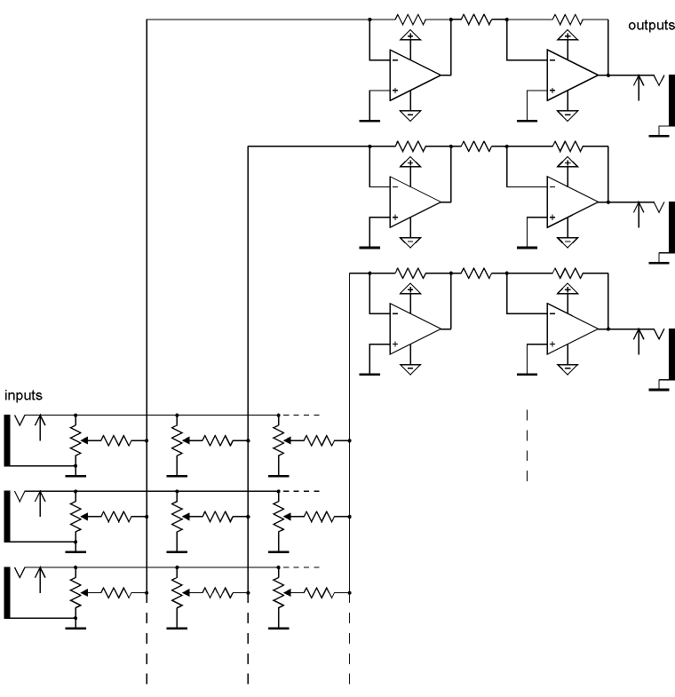
All operational amplifiers: LM1458, TL082, NE5532
All potentiometers: 47k linear (CV) or log (audio)
All resistors: 100k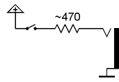

Search... ELectronics :
Circuit examples
Electronics Now
-
1. Power Amplifier Basic Circuit Characteristics Complementary symmetric OTL amplifier basic circuit as shown in Figure 1. Where: C1 for the...
-
The famous SGS-THOMSON ST Microelectronics has introduced a Hi-Fi DMOS high-power amplifier circuit TDA7294, its sound great taste bile, whi...
-
The fact that we need a subwoofer means that something is missing in the performance of the main speakers. This is not surprising, since the...
-
You have purchased construction quality Hi-Fi amplifier operating in class AB. Thanks to its small size, protected against short circuit on ...
-
Figure principle of good restructuring. The amp features: Changed the top, replacing self-made Indian plate of trouble. DC servo output DC-...
Categories
The creator of THIS PAGE or the ISP(s) hosting any content on this site take NO responsibility for the way you use the information provided on this site. These circuits here are for educational purposes only and SHOULD BE VIEWED ONLY. If you download any files to view them, you are agreeing to delete them within a 24 hour period. If you are affiliated with any government, or ANTI-Piracy group or any other related group or were formally a worker of one you CANNOT enter this web site, cannot access any of its files and you cannot view any of the HTML files. All the objects on this site are PRIVATE property and are meant for previewing only. If you enter this site without following these agreements you are not agreeing to these terms and you are violating code 431.322.12 of the Internet Privacy Act signed by Bill Clinton in 1995 and that means that you CANNOT threaten our ISP(s) or any person(s) or company storing these files, cannot prosecute any person(s) affiliated with this page which includes family, friends or individuals who run or enter this web site. IF YOU DO NOT AGREE TO THESE TERMS THEN LEAVE.
All files are found using legitimate search engine techniques. This site does not and will not condone hacking into sites to create the links it list. We will and do assume that all links found on the search engines we use are obtained in a legal manner and the webmasters are aware of the links listed on the search engines. If you find a URL that belongs to you, and you did not realize that it was "open to the public", please use the report button to notify the blogmaster of your request to remove it. This is not an invitation for webblog haters to spam with requests to remove content they feel that is objectionable and or unacceptable. Proof of URL ownership is required.
NOTICE: This Blog Has Already Been Reviewed And Accepted By Blogger.com

This work is licensed under a Creative Commons Attribution-NonCommercial-NoDerivs 3.0 Unported License.


0 comments:
Post a Comment