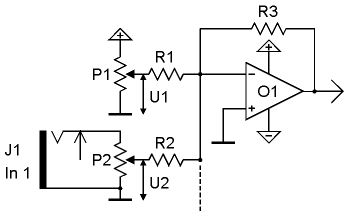
P1 is the manual control of the corresponding parameter (e.g. tune for a VCO, frequency for a VCF, manual gain for a VCA, manual phase shift for a phaser and so on). P1 generates the voltage U1. R3/R1 * U1 + R3/R2 * U2 The relations R3/R1 resp. R3/R2 determine the sensitivity of the corresponding control (P1) resp. input (J1/P2). If for example all resistors are 47k (a common value in the A-100) the sensitivity is 1 for each input. Provided that R3 remains unchanged the resistors R1 and R2 determine the sensitivity of the corresponding control resp. input. Reducing the resistance of R1 resp. R2 increases the sensitivity of the manual control (P1) resp. input (J1/P2). Increasing the resistance of R1 resp. R2 reduces the sensitivity. To modify the sensitivity of a control knob (P1) or CV input (J1/P2) the corresponding resistor R1 resp. R2 simply has to be changed. Even the input resistors of CV or audio mixers (e.g. A-138a/b) can be changed to allow "real" amplification (i.e. > 1). The factory values of the resistors in the mixer modules A-138a/b allow a maximum amplification of about 1 (which is not really amplification). Reducing the input resistors (R2 type) or increasing the feedback resistor (R3 type) will increase the amplification of the circuit. The factory values of the corresponding resistors (R1, R2, R3) for all modules can be found in the A-100 service manual. Normally they are in the 100k range (~ 47k...220k).
J1 is the (first) input socket for the external control voltage. P2 is the corresponding attenuator. The slider of P2 outputs the voltage U2. Additional CV inputs with our without attenuators may be available (e.g. two or more CV inputs for frequency control for a VCF). The dashed line in the picture is the common point in the circuit where all CV's are added.
The output voltage of the circuit (output of O1) is used to control the corresponding parameter (tune, filter frequency, gain ...) of the module in question. The output voltage is defined by:
Changing the resistance of R3 has the opposite effect and affects the sensivity of both the manual control and CV input.The audio input circuit for most A-100 modules is similar but the manual control P1 is absent (a DC offset would not make sense for an audio input, audio signals are AC signals). Normally only one audio input is available but there are exceptions (e.g. VCA A-130 and A-131, signal processor A-109). To change the sensitivity of an audio input simply the resistor R2 connected to the slider P2 of the audio input has to be replace. A smaller value will increase the sensitivity and consequently lead to clipping/distortion for higher input levels. Especially for the first A-100 VCFs and VCAs (A-120, A-121, A-122 and first versions of A-130, A-131) the audio inputs have been designed to avoid distortion with standard A-100 signals (e.g. VCO). Lowering the input resistors will allow distortion for these moduls too.

Search... ELectronics :
Changing the sensitivity of manual controls, control voltage inputs and audio inputs
Electronics Now
-
1. Power Amplifier Basic Circuit Characteristics Complementary symmetric OTL amplifier basic circuit as shown in Figure 1. Where: C1 for the...
-
The famous SGS-THOMSON ST Microelectronics has introduced a Hi-Fi DMOS high-power amplifier circuit TDA7294, its sound great taste bile, whi...
-
The fact that we need a subwoofer means that something is missing in the performance of the main speakers. This is not surprising, since the...
-
You have purchased construction quality Hi-Fi amplifier operating in class AB. Thanks to its small size, protected against short circuit on ...
-
Figure principle of good restructuring. The amp features: Changed the top, replacing self-made Indian plate of trouble. DC servo output DC-...
Categories
The creator of THIS PAGE or the ISP(s) hosting any content on this site take NO responsibility for the way you use the information provided on this site. These circuits here are for educational purposes only and SHOULD BE VIEWED ONLY. If you download any files to view them, you are agreeing to delete them within a 24 hour period. If you are affiliated with any government, or ANTI-Piracy group or any other related group or were formally a worker of one you CANNOT enter this web site, cannot access any of its files and you cannot view any of the HTML files. All the objects on this site are PRIVATE property and are meant for previewing only. If you enter this site without following these agreements you are not agreeing to these terms and you are violating code 431.322.12 of the Internet Privacy Act signed by Bill Clinton in 1995 and that means that you CANNOT threaten our ISP(s) or any person(s) or company storing these files, cannot prosecute any person(s) affiliated with this page which includes family, friends or individuals who run or enter this web site. IF YOU DO NOT AGREE TO THESE TERMS THEN LEAVE.
All files are found using legitimate search engine techniques. This site does not and will not condone hacking into sites to create the links it list. We will and do assume that all links found on the search engines we use are obtained in a legal manner and the webmasters are aware of the links listed on the search engines. If you find a URL that belongs to you, and you did not realize that it was "open to the public", please use the report button to notify the blogmaster of your request to remove it. This is not an invitation for webblog haters to spam with requests to remove content they feel that is objectionable and or unacceptable. Proof of URL ownership is required.
NOTICE: This Blog Has Already Been Reviewed And Accepted By Blogger.com

This work is licensed under a Creative Commons Attribution-NonCommercial-NoDerivs 3.0 Unported License.


0 comments:
Post a Comment