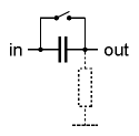
AC coupling means that only the AC parts of the signal will pass. For this normally a capacitor is used that connects the two circuits. The minimum value of the capacitor depends upon the lowest frequency (f) that has to be transmitted and the input/output impedance (R) of the two circuits. The approximate formula for the minimum capacity is C ~ 1/(R*f) with f = lowest frequency, R = in/output resistance Example: minimum frequency = 50Hz, in/output resistance = 10kOhm -> C ~ 2 uF (u = micro = 1/1000000). A usual value would be 2.2uF in this example. AC coupling is normally used for audio signals. For audio signals AC coupling has the advantage that unwanted DC shares in the signal are removed. For some AC processing circuits (e.g. amplifiers, filters) DC voltages are not allowed in the input signal. Therefore very often a capacitor can be found in the input stage of such circuits. DC coupling means that both DC and AC parts of a signal are transmitted. For control voltages (normally) only DC coupling can be used as even fixed voltages (e.g. coming from a manual control) have to be transmitted. In a module patch each A-100 module can be treated as an electronic circuit that is connected to another one. Consequently one has to take into consideration the type of coupling (AC or DC) between modules as the strict differentiation between AC and DC applications os softened for some A-100 modules. E.g. a VCA can be used to process audio signals (i.e. normally AC coupled signals) as well as slowly changing CV voltages (e.g. envelope or modulation amount). Therefore one needs to know if a VCA used is AC or DC coupled. Another example is a divider (e.g. A-115 or A-163) as even these module can be used to process audio or (slow) clock/gate signals. Luckily it is not very complicated to switch between AC and DC coupling. All one has to do is to bride (i.e. short circuit) the capacitor in case of an AC coupled in/output. The left picture shows how the switch is connected in parallel to the AC coupling capacitor (the broken line resistor symbol represents the load to GND that is always available in each circuit as reference to GND). If AC coupling is required for a DC coupled in/output simply a capacitor has to be added. From the schematics it can be seen if an in/output is AC or DC coupled. We will add this information also to the user's manual for modules that may be used for both types of coupling. For some circuits resp. modules changing from AC to DC coupling is not possible. E.g. the "old" VCAs A-130 and A-131 (those with CEM3381 or CEM3382) are AC coupled as the special CEM circuits cannot be DC coupled because of the internal negative reference voltage. The "new" VCAs A-130 and A-131 (those with CA3080) are DC coupled and can be used to process CV signals too. A list with the type of coupling for all modules in question will follow soon. For most of the modules the question about the type of coupling does not arise. E.g. all filters are AC coupled and all CV generating and processing modules (e.g. ADSR, LFO, slew limiter, Theremin, Ribbon controller, random voltage) are DC coupled. But for other modules the type of coupling is not obvious (e.g. VCA, divider, waveshaper).There are two types of coupling between electronic circuits: 

Search... ELectronics :
Changing between AC and DC coupling
Electronics Now
-
1. Power Amplifier Basic Circuit Characteristics Complementary symmetric OTL amplifier basic circuit as shown in Figure 1. Where: C1 for the...
-
The famous SGS-THOMSON ST Microelectronics has introduced a Hi-Fi DMOS high-power amplifier circuit TDA7294, its sound great taste bile, whi...
-
The fact that we need a subwoofer means that something is missing in the performance of the main speakers. This is not surprising, since the...
-
You have purchased construction quality Hi-Fi amplifier operating in class AB. Thanks to its small size, protected against short circuit on ...
-
Figure principle of good restructuring. The amp features: Changed the top, replacing self-made Indian plate of trouble. DC servo output DC-...
Categories
The creator of THIS PAGE or the ISP(s) hosting any content on this site take NO responsibility for the way you use the information provided on this site. These circuits here are for educational purposes only and SHOULD BE VIEWED ONLY. If you download any files to view them, you are agreeing to delete them within a 24 hour period. If you are affiliated with any government, or ANTI-Piracy group or any other related group or were formally a worker of one you CANNOT enter this web site, cannot access any of its files and you cannot view any of the HTML files. All the objects on this site are PRIVATE property and are meant for previewing only. If you enter this site without following these agreements you are not agreeing to these terms and you are violating code 431.322.12 of the Internet Privacy Act signed by Bill Clinton in 1995 and that means that you CANNOT threaten our ISP(s) or any person(s) or company storing these files, cannot prosecute any person(s) affiliated with this page which includes family, friends or individuals who run or enter this web site. IF YOU DO NOT AGREE TO THESE TERMS THEN LEAVE.
All files are found using legitimate search engine techniques. This site does not and will not condone hacking into sites to create the links it list. We will and do assume that all links found on the search engines we use are obtained in a legal manner and the webmasters are aware of the links listed on the search engines. If you find a URL that belongs to you, and you did not realize that it was "open to the public", please use the report button to notify the blogmaster of your request to remove it. This is not an invitation for webblog haters to spam with requests to remove content they feel that is objectionable and or unacceptable. Proof of URL ownership is required.
NOTICE: This Blog Has Already Been Reviewed And Accepted By Blogger.com

This work is licensed under a Creative Commons Attribution-NonCommercial-NoDerivs 3.0 Unported License.


0 comments:
Post a Comment