
Resistor
From Wikipedia, the free encyclopedia
A resistor is a two-terminal electronic component designed to oppose an electric current by producing a voltage drop between its terminals in proportion to the current, that is, in accordance with Ohm's law: V = IR. The resistance R is equal to the voltage drop V across the resistor divided by the current I through the resistor.
Resistors are characterized primarily by their resistance and the power they can dissipate. Other characteristics include temperature coefficient, noise, and inductance. Practical resistors can be made of resistive wire, and various compounds and films, and they can be integrated into hybrid and printed circuits. Size, and position of leads are relevant to equipment designers; resistors must be physically large enough not to overheat when dissipating their power. Variable resistors, adjustable by changing the position of a tapping on the resistive element, and resistors with a movable tap ("potentiometers"), either adjustable by the user of equipment or contained within, are also used.
Resistors are used as part of electrical networks and electronic circuits.
There are special types of resistor whose resistance varies with various quantities, most of which have names, and articles, of their own: the resistance of thermistors varies greatly with temperature, whether external or due to dissipation, so they can be used for temperature or current sensing; metal oxide varistors drop to a very low resistance when a high voltage is applied, making them suitable for over-voltage protection; the resistance of a strain gauge varies with mechanical load; the resistance of photoresistors varies with illumination; the resistance of a Quantum Tunnelling Composite can vary by a factor of 1012 with mechanical pressure applied; and so on.
Units
The ohm (symbol: Ω) is the SI unit of electrical resistance, named after Georg Ohm. The most commonly used multiples and submultiples in electrical and electronic usage are the milliohm, ohm, kilohm, and megohm.
Technology
Carbon composition
Carbon composition resistors consist of a solid cylindrical resistive element with embedded wire leadouts or metal end caps to which the leadout wires are attached, which is protected with paint or plastic.
The resistive element is made from a mixture of finely ground (powdered) carbon and an insulating material (usually ceramic). A resin holds the mixture together. The resistance is determined by the ratio of the fill material (the powdered ceramic) and the carbon. Higher concentrations of carbon, a weak conductor, result in lower resistance. Carbon composition resistors were commonly used in the 1960s and earlier, but are not so popular for general use now as other types have better specifications, such as tolerance, voltage dependence, and stress (carbon composition resistors will change value when stressed with over-voltages).
Carbon film
A carbon film is deposited on an insulating substrate, and a spiral cut in it to create a long, narrow resistive path. Varying shapes, coupled with the resistivity of carbon, (ranging from 9 to 40 µΩm) can provide a variety of resistances. Carbon film resistors feature a power rating range of 1/6 W to 5 W at 70°C. Resistances available range from 1 ohm to 10M ohm. The carbon film resistor can operate between temperatures of -55°C to 155°C. It has 200 to 600 volts maximum working voltage range.[2]
Thick and thin film
Thick film resistors became popular during the 1970s, and most SMD resistors today are of this type. The principal difference between thin film and thick film resistors is not the actual thickness of the film, but rather how the film is applied to the cylinder (axial resistors) or the surface (SMD resistors).
Thin film resistors are made by sputtering the resistive material onto an insulating substrate Sputtering is a method used in vacuum deposition. The film is then etched in a similar manner to the old (subtractive) process for making printed circuit boards: i.e. the surface is coated with a photo-sensitive material, then covered by a film, irradiated with ultraviolet light, and then the exposed photo-sensitive coating, and underlying thin film, are etched away.
Because the time during which the sputtering is performed can be controlled, the thickness of the thin film can be accurately controlled. The type of material is also usually different consisting of one or more ceramic (cermet) conductors such as tantalum nitride (TaN), ruthenium dioxide (RuO2), lead oxide (PbO), bismuth ruthenate (Bi2Ru2O7), nickel chromium (NiCr), and/or bismuth iridate (Bi2Ir2O7).
The resistance of both thin and thick film resistors after manufacture is not highly accurate; they are usually trimmed to an accurate value by abrasive or laser trimming. Thin film resistors are usually specified with tolerances of 0.1, 0.2, 0.5, or 1%, and with temperature coefficients of 5 to 25 ppm/K.
Thick film resistors may use the same conductive ceramics, but they are mixed with sintered (powdered) glass and some kind of liquid so that the composite can be screen-printed. This composite of glass and conductive ceramic (cermet) material is then fused (baked) in an oven at about 850 °C.
Thick film resistors, when first manufactured, had tolerances of 5%, but in the last few decades standard tolerances have improved to 2% or 1%. Temperature coefficients of thick film resistors are high, typically ±200 or ±250 ppm/K; a 40 kelvin (70°F) temperature change can change the resistance by 1%.
Thin film resistors are usually far more expensive than thick film resistors, although, for example, SMD thin film resistors, with 0.5% tolerances, and with 25 ppm/K temperature coefficients, when bought in full size reel quantities, are about twice the cost of 1%, 250 ppm/K thick film resistors.
Metal film
A common type of axial resistor today is referred to as a metal-film resistor. MELF (Metal Electrode Leadless Face) resistors often use the same technology, but are a cylindrically shaped resistor designed for surface mounting. [Note that other types of resistors, e.g. carbon composition, are also available in "MELF" packages].
Metal film resistors are usually coated with nickel chromium (NiCr), but might be coated with any of the cermet materials listed above for thin film resistors. Unlike thin film resistors, the material may be applied using different techniques than sputtering (though that is one such technique). Also, unlike thin-film resistors, the resistance value is determined by cutting a helix through the coating rather than by etching. [This is similar to the way carbon resistors are made.] The result is a reasonable tolerance (0.5, 1, or 2%) and a temperature coefficient of (usually) 25 or 50 ppm/K.
Wirewound
Wirewound resistors are commonly made by winding a metal wire around a ceramic, plastic, or fiberglass core. The ends of the wire are soldered or welded to two caps, attached to the ends of the core. The assembly is protected with a layer of paint, molded plastic, or an enamel coating baked at high temperature. The wire leads are usually between 0.6 and 0.8 mm in diameter and tinned for ease of soldering. For higher power wirewound resistors, either a ceramic outer case or an aluminum outer case on top of an insulating layer is used. The aluminum-cased types are designed to be attached to a heatsink to dissipate the heat; the rated power is dependent on being used with a suitable heatsink, e.g., a 50 W power rated resistor will overheat at around one fifth of the power dissipation if not used with a heatsink.
Because wirewound resistors are coils they have more undesirable inductance than other types of resistor, although inductance can be minimized by winding the wire in sections with alternately reversed direction.
Foil resistor
The primary resistance element of foil resistors is a special alloy foil several micrometres thick. Foil resistors have had the best precision and stability ever since they were introduced in 1962 by Felix Zandman. One of the important parameters influencing stability is the temperature coefficient of resistance (TCR). The TCR of foil resistors is extremely low, and has been further improved over the years.[3] One range of ultra-precision foil resistors offers a TCR of 0.14ppm/°C, tolerance ±0.005%, long-term stability 25ppm/year, 50ppm/3 years (further improved 5-fold by hermetic sealing), stability under load 0.03%/2000 hours, thermal EMF 0.1μvolt/°C, noise -42dB, voltage coefficient 0.1ppm/V, inductance 0.08μH, capacitance 0.5pF[1].
Current sensing resistor
A current sensing resistor (CSR) is essentially a normal resistor optimized to monitor the current flowing through a circuit by a very simple application of Ohm's law: the voltage drop across the resistor, which is measured, is equal to the product of the current through it by the resistance[2]. The resistance of the CSR is selected so as to produce a voltage drop small enough not to interfere with circuit operation, but large enough to be measurable to the required accuracy. Typical values range from 0.004 to 0.1 ohm. These resistors are designed with tight tolerance, low temperature coefficient, and low thermal EMF for maximum accuracy. For the most exacting cases 4-terminal resistors are manufactured, with one pair of terminals providing the path for the current to be measured, and the other for connecting to the measurement circuit; this is common practice with precision standard resistances used at measurement standards laboratories. 4-terminal construction minimizes lead resistance, TCR of copper terminals, and TCR of solder joints.
Construction materials and configuration style are important parameters to consider. Materials include carbon composition, carbon film, ceramic composition, metal alloy, metal film, thick film (chip), thin film (chip) and wire-wound. Configuration styles include single resistor, resistor network, and resistor chip array. Single current sensing resistors have a single resistance value. Current sensing resistor networks feature a pin layout with multiple resistors connected in series. Current sensing resistor chip arrays connect multiple resistors in parallel.
Specified properties of current sensing resistors may include resistance, number of terminals, tolerance, power rating, continuous operating voltage, temperature coefficient parameter (TCP), and operating temperature. Single current resistors may have either two or four terminals. Resistance range is measured in ohms. Tolerance is specified as percentage. Power rating is the maximum power level that a current sensing resistor can dissipate. The continuous operating voltage is measured in volts. The temperature coefficient parameter (TCP) measures the rate at which the nominal resistance value changes as a function of temperature. Typically, TCP is expressed as parts-per-million per degree Celsius (ppm/C). Operating temperature is an important environmental parameter to consider, especially for current sensing resistors that are exposed to flow, reflow, or wave soldering.
Grid resistor
In heavy-duty industrial high-current applications, a grid resistor is a large convection-cooled lattice of stamped metal alloy strips connected in rows between two electrodes. Such industrial grade resistors can be as large as a refrigerator; some designs can handle over 500 amperes of current, with a range of resistances extending lower than 0.04 Ohms. They are used in applications such as dynamic braking and load banking for locomotives and trams, neutral grounding for industrial AC distribution, control loads for cranes and heavy equipment, load testing of generators and harmonic filtering for electric substations.[4][5][6]
The term "grid resistor" is sometimes used to describe a resistor of any type connected to the control grid of a vacuum tube. This is not, however, a resistor technology.
Strain gauges
The strain gauge, invented by Edward E. Simmons and Arthur C. Ruge in 1938, is a type of resistor that changes value with applied strain. A single resistor may be used, or a pair (half bridge), or four resistors connected in a Wheatstone bridge configuration. The strain resistor is bonded with adhesive to an object that will be subjected to mechanical strain. With the strain gauge and a filter, amplifier, and analog/digital converter, the strain on an object can be measured.
Negative resistors
A device exhibiting negative resistance over part of its characteristic curve can be made with active circuit components.
Other types
Power dissipation
The power dissipated by a resistor is the voltage across the resistor multiplied by the current through the resistor:
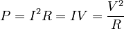
All three equations are equivalent. The first is derived from Joule's law, and the other two are derived from that by Ohm's Law.
The total amount of heat energy released is the integral of the power over time:

If the average power dissipated is more than the resistor can safely dissipate, the resistor may depart from its nominal resistance, and may be damaged by overheating. Excessive power dissipation may raise the temperature of the resistor to a point where it burns out, which could cause a fire in adjacent components and materials.
Note that the nominal power rating of a resistor is not the same as the power that it can safely dissipate in practical use. Air circulation and proximity to a circuit board, ambient temperature, and other factors can reduce acceptable dissipation very significantly. Rated power dissipation may be given for an ambient temperature of 25°C in free air. Inside an equipment case at 60°C, rated dissipation will be significantly less; if we are dissipating a bit less than the maximum figure given by the manufacturer we may still be outside the safe operating area, and courting premature failure.
Series and parallel resistors
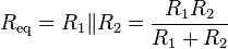
Resistors in a parallel configuration each have the same potential difference (voltage). To find their total equivalent resistance (Req):


The parallel property can be represented in equations by two vertical lines "||" (as in geometry) to simplify equations. For two resistors,
The current through resistors in series stays the same, but the voltage across each resistor can be different. The sum of the potential differences (voltage) is equal to the total voltage. To find their total resistance:


A resistor network that is a combination of parallel and series can sometimes be broken up into smaller parts that are either one or the other. For instance,


However, many resistor networks cannot be split up in this way. Consider a cube, each edge of which has been replaced by a resistor. For example, determining the resistance between two opposite vertices requires matrix methods for the general case. However, if all twelve resistors are equal, the corner-to-corner resistance is 5⁄6 of any one of them.
The practical application to resistors is that a resistance of any non-standard value can be obtained by connecting standard values in series or in parallel.
Resistor standards
Production resistors
There are various standards specifying properties of resistors for use in equipment:
- BS 1852
- EIA-RS-279
- MIL-PRF-26
- MIL-PRF-39007
- MIL-PRF-55342
- MIL-PRF-914
- MIL-R-11
- MIL-R-39008
- MIL-R-39017
There are other United States military procurement MIL-R- standards.
Resistance standards
Resistors of extremely high precision are manufactured as substandards of resistance for calibration and laboratory use. They may have 4 terminals, using one pair to carry an operating current, and the other pair to measure the voltage drop; this minimizes temperature coefficients and thermal EMFs. The data sheet for a resistance standard used for calibration is here.
Resistance decade boxes
A resistance decade box is a box containing resistors of many values and two (or four) terminals, with a mechanical switch that allows a resistance of any value allowed by the box to be dialed. Usually the resistance is accurate to high precision, ranging from laboratory/calibration grade accurate to within 20 parts per million, to field grade at 1%. Inexpensive boxes with lesser accuracy are also available. All types offer a convenient way of selecting and quickly changing a resistance in laboratory, experimental and development work without having to stock and seek individual resistors of the required value. The range of resistance provided, the maximum resolution, and the accuracy characterize the box. For example, one box offers resistances from 0 to 24 megohms, maximum resolution 0.1 ohm, accuracy 0.1%.
Resistor marking
Most axial resistors use a pattern of colored stripes to indicate resistance. Surface-mount resistors are marked numerically. Cases are usually tan, brown, blue, or green, though other colors are occasionally found such as dark red or dark gray.
The value of a resistor can be measured with an ohmmeter, which may be one function of a multimeter.
Four-band axial resistors
Four-band identification is the most commonly used color-coding scheme on all resistors. It consists of four colored bands that are painted around the body of the resistor. The first two bands encode the first two significant digits of the resistance value, the third is a power-of-ten multiplier or number-of-zeroes, and the fourth is the tolerance accuracy, or acceptable error, of the value. Sometimes a fifth band identifies the thermal coefficient, but this must be distinguished from the true 5-color system, with 3 significant digits.
For example, green-blue-yellow-red is 56×104 Ω = 560 kΩ ± 2%. An easier description can be as followed: the first band, green, has a value of 5 and the second band, blue, has a value of 6, and is counted as 56. The third band, yellow, has a value of 104, which adds four 0's to the end, creating 560,000Ω at ±2% tolerance accuracy. 560,000Ω changes to 560 kΩ ±2% (as a kilo- is 103).
Each color corresponds to a certain digit, progressing from darker to lighter colors, as shown in the chart below.
| Color | 1st band | 2nd band | 3rd band (multiplier) | 4th band (tolerance) | Temp. Coefficient |
|---|---|---|---|---|---|
| Black | 0 | 0 | ×100 | ||
| Brown | 1 | 1 | ×101 | ±1% (F) | 100 ppm |
| Red | 2 | 2 | ×102 | ±2% (G) | 50 ppm |
| Orange | 3 | 3 | ×103 | 15 ppm | |
| Yellow | 4 | 4 | ×104 | 25 ppm | |
| Green | 5 | 5 | ×105 | ±0.5% (D) | |
| Blue | 6 | 6 | ×106 | ±0.25% (C) | |
| Violet | 7 | 7 | ×107 | ±0.1% (B) | |
| Gray | 8 | 8 | ×108 | ±0.05% (A) | |
| White | 9 | 9 | ×109 | ||
| Gold | ×10-1 | ±5% (J) | |||
| Silver | ×10-2 | ±10% (K) | |||
| None | ±20% (M) |
Preferred values
Early resistors were made in more or less arbitrary round numbers; a series might have 100, 125, 150, 200, 300, etc. Resistors as manufactured are subject to a certain percentage tolerance, and it makes sense to manufacture values that correlate with the tolerance, so that the actual value of a resistor overlaps slightly with its neighbors. Wider spacing leaves gaps; narrower spacing increases manufacturing and inventory costs to provide resistors that are more or less interchangeable.
A logical scheme is to produce resistors in a range of values which increase in a geometrical progression, so that each value is greater than its predecessor by a fixed multiplier, chosen to match the tolerance of the range. For example, for a tolerance of ±20% it makes sense to have each resistor about 1.5 times its predecessor, covering a decade in 6 values. In practice the factor used is 1.4678, giving values of 1.47, 2.15, 3.16, 4.64, 6.81, 10 for the 1-10 decade (a decade is a range increasing by a factor of 10; 0.1-1 and 10-100 are other examples); these are rounded in practice to 1.5, 2.2, 3.3, 4.7, 6.8, 10; followed, of course by 15, 22, 33, … and preceded by … 0.47, 0.68, 1. This scheme has been adopted as the E6 range of the IEC 60063 preferred number series. There are also E12, E24, E48, E96 and E192 ranges for components of ever tighter tolerance, with 12, 24, 96, and 192 different values within each decade. The actual values used are in the IEC 60063 lists of preferred numbers.
A resistor of 100-ohms±20% would be expected to have a value between 80 and 120 ohms; its E6 neighbors are 68 (54-82) and 150 (120-180) ohms. A sensible spacing. E6 is used for ±20% components; E12 for ±10%; E24 for ±5%; E48 for ±2%, E96 for ±1%; E192 for ±0.5% or better. Resistors are manufactured in values from a few milliohms to about a gigaohm in IEC60063 ranges appropriate for their tolerance.
5-band axial resistors
5-band identification is used for higher precision (lower tolerance) resistors (1%, 0.5%, 0.25%, 0.1%), to specify a third significant digit. The first three bands represent the significant digits, the fourth is the multiplier, and the fifth is the tolerance. Five-band resistors with a gold or silver 4th band are sometimes encountered, generally on older or specialized resistors. The 4th band is the tolerance and the 5th the temperature coefficient.
SMT resistors
Surface mounted resistors are printed with numerical values in a code related to that used on axial resistors. Standard-tolerance Surface Mount Technology (SMT) resistors are marked with a three-digit code, in which the first two digits are the first two significant digits of the value and the third digit is the power of ten (the number of zeroes). For example:
| "334" | = 33 × 10,000 ohms = 330 kilohms |
| "222" | = 22 × 100 ohms = 2.2 kilohms |
| "473" | = 47 × 1,000 ohms = 47 kilohms |
| "105" | = 10 × 100,000 ohms = 1 megohm |
Resistances less than 100 ohms are written: 100, 220, 470. The final zero represents ten to the power zero, which is 1. For example:
| "100" | = 10 × 1 ohm = 10 ohms |
| "220" | = 22 × 1 ohm = 22 ohms |
Sometimes these values are marked as "10" or "22" to prevent a mistake.
Resistances less than 10 ohms have 'R' to indicate the position of the decimal point (radix point). For example:
| "4R7" | = 4.7 ohms |
| "0R22" | = 0.22 ohms |
| "0R01" | = 0.01 ohms |
Precision resistors are marked with a four-digit code, in which the first three digits are the significant figures and the fourth is the power of ten. For example:
| "1001" | = 100 × 10 ohms = 1 kilohm |
| "4992" | = 499 × 100 ohms = 49.9 kilohm |
| "1000" | = 100 × 1 ohm = 100 ohms |
"000" and "0000" sometimes appear as values on surface-mount zero-ohm links, since these have (approximately) zero resistance.
Industrial type designation
Format: [two letters]
| Type No. | Power rating (watts) | MIL-R-11 Style | MIL-R-39008 Style |
|---|---|---|---|
| BB | 1/8 | RC05 | RCR05 |
| CB | ¼ | RC07 | RCR07 |
| EB | ½ | RC20 | RCR20 |
| GB | 1 | RC32 | RCR32 |
| HB | 2 | RC42 | RCR42 |
| GM | 3 | - | - |
| HM | 4 | - | - |
| Industrial type designation | Tolerance | MIL Designation |
|---|---|---|
| 5 | ±5% | J |
| 2 | ±20% | M |
| 1 | ±10% | K |
| - | ±2% | G |
| - | ±1% | F |
| - | ±0.5% | D |
| - | ±0.25% | C |
| - | ±0.1% | B |
The operational temperature range distinguishes commercial grade, industrial grade and military grade components.
- Commercial grade: 0 °C to 70 °C
- Industrial grade: −40 °C to 85 °C (sometimes −25 °C to 85 °C)
- Military grade: −55 °C to 125 °C (sometimes -65 °C to 275 °C)
- Standard Grade -5°C to 60°C
Electrical noise
In precision circuits it is often necessary to minimize electronic noise. As dissipative elements, even ideal resistors will naturally produce a fluctuating "noise" voltage across their terminals. This Johnson–Nyquist noise is a fundamental noise source which depends only upon the temperature and resistance of the resistor, and is predicted by the fluctuation–dissipation theorem. For example, the gain in a simple (non-) inverting amplifier is set using a voltage divider. Noise considerations dictate that the smallest practical resistance should be used, since the Johnson–Nyquist noise voltage scales with resistance, and any resistor noise in the voltage divider will be impressed upon the amplifier's output.
In addition to this intrinsic noise, practical resistors frequently exhibit other, "non-fundamental", sources of noise, usually called "excess noise." Thick-film and carbon composition resistors generate more noise than other types at low frequencies; wire-wound and thin-film resistors, though much more expensive, are often utilized for their better noise characteristics.
Precautions required in high-precision applications
Various effects become important in high-precision applications. Small voltage differentials may appear on the resistors due to thermoelectric effect if their ends are not kept at the same temperature. The voltages appear in the junctions of the resistor leads with the circuit board and with the resistor body. Common metal film resistors show such effect at magnitude of about 20 µV/°C. Some carbon composition resistors can go as high as 400 µV/°C, and specially constructed resistors can go as low as 0.05 µV/°C. In applications where thermoelectric effects may become important, care has to be taken (for example) to mount the resistors horizontally to avoid temperature gradients and to mind the air flow over the board.[8]
Failure modes
Like every part, resistors can fail in normal use. Thermal and mechanical stress, humidity, etc., can play a part. Carbon composition resistors and metal film resistors typically fail as open circuits. Carbon-film resistors may decrease or increase in resistance.[9] Carbon film and composition resistors can open if running close to their maximum dissipation. This is also possible but less likely with metal film and wirewound resistors. If not enclosed, wirewound resistors can corrode. Carbon composition resistors are prone to drifting over time and are easily damaged by excessive heat in soldering (the binder evaporates). Variable resistors become electrically noisy as they wear.
All resistors can be destroyed, usually by going open-circuit, if subjected to excessive current due to failure of other components or accident.


0 comments:
Post a Comment