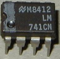

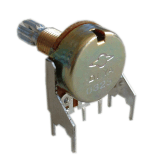
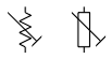
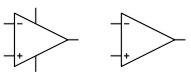
(For some parts different signs are shown. Normally the left one is used in USA or Japan, the right one in Germany or Europe) Fixed resistors A resistor is determinded by these parameters: value (... Ohm, ... kOhm, ... MOhm, usual abbreviations kOhm = k and MOhm =M, e.g. 2.2 kOhm = 2.2k or 2k2) power (.. mW, ...W) tolerance (%) max. voltage dimensions (e.g. length, diameter and especially the grid between the legs on the pc board) In the A-100 normally only resistors with 1/4W (250mW) and 5%, 1% or 0.1% tolerance are used. For the value and tolerance of a resistor normally a color code is used (should we add the color code at this place ?). Potentiometers Potentiometers are available as rotary potentiometers or fader types. Normally, a potentiometer has 3 terminals: two end terminals and a slider terminal (upper picture). The slider touches a resistance surface that is located between the end terminals. Sometimes the second end terminal is not shown (lower picture) if only one end terminal is required, e.g. if the part works only as a variable resistor rather than a voltage divider. A potentiometer is determined by these parameters: value (... Ohm, ... kOhm, ... MOhm) power (.. mW, ...W) tolerance (%) characteristics (law) mechanical dimensions (e.g. diameter, type, length and material of the axis, distance and diameter of the holes required on the pc board, position of auxiliary terminals without electronic function and so on) The characteristics - sometimes even called law - is a very important parameter of a potentiometer. This parameter describes the connection between the rotary angle (resp. fader position for fader potentiometers) and the resistance value between terminal 1 and slider terminal. Typical characteristics are linear, logarithmic and inverse logarithmic. Sometimes special characteristics are used (e.g. S-type law) but these are not very common. For audio attenuation normally logarithmic potentiometers are used as the human ear senses the loudness of an audio signal in a logarithmic way too. The same applies to potentiometers that are used to control time parameters (e.g. attack/decay/release time of an envelope generator). For attenuation of control signals normally linear potentiometers are used. For special functions inverse logarithmic potentiometers are used (e.g. resonance/emphasis control in filter circuits). A very special circuit is a so-called vactrol. This is a combination of a light depending resistor (LDR) and LED both put into a small 100% light-proof case. For details please refer to the vactrol document. The above pictures shows the type of potentiometers used in the A-100 system. These potentiometers are equipped with a mounting bracket that increases the mechanical stability. For most of the A-100 modules the potentiometers (together with the sockets) are used to mount the pc boards to the front panels. Trimming potentiometers The electronic function of a "normal" potentiometer and a trimming potentiometer is the same. The only difference is the mechanical appearance: trimming potentiometers are normally much smaller and have a very short axis that is adjusted with a screw driver. Trimming potentiometers are used to adjust parameters that have to bet set once at the factory and that are normally not controlled by the user (e.g. offset frequency and scale of a VCO, maximum/minimum limitation of values, adjustment of click/pop feedthrough of sound processing devices like VCA, VCF, ring modulator, frequency shifters and so on). Sometimes users replace trimming potentiometers with normal ones to have access to such additional parameters. Capacitors A capacitor is determinded by these parameters: value (... pF/picofarad, ... nF/nanofarad, ... uF/microfarad, usual abbreviations pF =p, nF =n, uF =u, 2.2 nF = 2.2n or 2n2) type of dielectric (foil, ceramic, multilayer, electrolytic) tolerance (%) max. voltage polarized/non polarized (electrolytic capacitors are normally polarized) dimensions (e.g. length/width/height or length/diameter and especially the grid between the legs on the pc board) In the A-100 all types of capacitors are used. Value, voltage and tolerance are normally written as normal characters on the component (e.g. 4n7 63V). But even color codes and number codes are used (e.g. 103 means 10x1000=10000). Sometimes it is difficult to find the value of a capacitor. E.g. "100" without additional pF/nF could mean 100pF or 100nF. Some experience is required to find out the correct value if the declaration on the component is not readable, or complete. To be certain of a capacitors value, one could use a capacitor measuring instrument such as a multimeter with capacitor measuring option. So-called electrolytic capacitors are used for values of 1uF and more as the other types of capacitors would be too large. Normally electrolytic capacitors are polarized (i.e. one has to pay attention to positive and negative terminal of the part). If there are "+" or "-" signs in a schematic this means that an electrolytic capacitor is used. The three examples on the left with "+" and "-" signs denote an electrolytic capacitor. Other types of capacitors (e.g. variable capacitors) are not used in the A-100. Diodes Electronic part that works as one-way for electric current. The triangle terminal (left) of the symbol is the positive side (or anode), the single vertical line (right) is the negative terminal (or cathode). Used e.g. for clipping, rectifying or overvoltage protection. Even light emitting versions (LED) available in different colors (red, green, yellow, orange, blue, white). In this case the brightness is approximately proportional to the current. A very special circuit is a so-called vactrol. This is a combination of a light depending resistor (LDR) and LED both put into a small 100% light-proof case. For details please refer to the vactrol document. Transistors Different types of transistors are available, e.g. bipolar npn or pnp, field effect (FET). A transistor can be used with the suitable circuit (i.e. with additional resistors and capacitors) e.g. as amplifier, switch or current source. Operational Amplifiers Operational amplifiers are special integrated circuits that make available a standard amplifier with 2 inputs (inverting and non-inverting input) and high amplification (typ. > 1000). Circuits with one, two or more opamps (abbreviation for operational amplifier) are available. The following table shows the pin-out of the most popular types of single, dual and quad opamps. e.g. uA741, TL061, TL071, TL081, TLC271, NE5534, LF411, LF351, LF356 e.g. uA747, LM1458, LM4558, TL062, TL072, TL082, TLC272, NE5532, LF412, LF353 e.g. LM124, LM224, LM324, TL064, TL074, TL084, TLC274, LF444 The power supply pins (marked with the "+" and "-" triangles) of the integrated circuit in question have to be connected to +12V and -12V for A-100 applications. In schematics the power supply pins of opamps are often omitted. The left opamp symbol includes the power supply pins. The right symbol is without the power supply pins. Switches A lot of different switches are available. There exist different distinguishing marks, e.g.: type of operation: momentary or permanent number of terminals number of parallel switches number of positions The pictures show from top to bottom the symbols for a simple on/off switch (SPDT with one ON contact only) , a change-over switch (SPDT with two ON contacts), a rotary switch with 3 positions, a change-over switch with middle position (SPDT with ON-OFF-ON) and a rotary switch witch 5 positions. Jack sockets Standard sockets used in the A-100 for all inputs and outputs. Provided that a plug is inserted into the socket the GND and tip terminals of the plug are connected to the corresponding terminals of the socket. The tip is normally the "hot" pin, i.e. the terminal leading the CV resp. audio signal. The sockets are equipped with switching contacts (the arrow in the symbol). Both the GND and tip terminal are switched but only the switching feature of the tip terminal is used in some A-100 modules. Provided that no plug is inserted into the socket the switched tip contact (arrow terminal in the left symbol) is connected to the "normal" tip contact (the terminal represented by the horizontal line in the left symbol). As soon as a plug is inserted this connection is interrupted and the signal at the tip of the plug is connected to the tip terminal of the socket. This feature can be used for default connections (i.e. connection within a module that is established provided that no plug is inserted into the corresponding socket). Example: internal default connections of the A-109 signal processor. This function is often called "normalling" or "normalizing". The above pictures show the type of jack sockets used in the A-100 system. For most of the A-100 modules the sockets (together with the potentiometers) are used to mount the pc boards to the front panels. The A-100 sockets are available as spare parts. For prices please look at the price list. Power Supply For each circuit, a power supply is required. The three symbols to the left side denote +12V, -12V and GND. Some circuits may require no power supply (e.g. multiples or the simple attenuator below) or only a positive supply. All circuits that use operational amplifiers require all three +12V, GND and -12V. Some modules even require +5V (mainly "digital" modules with digital circuits - like microprocessors, memories, or logic circuits - which often require a +5V power supply). ![]()


Another special type is a stereo potentiometer: two potentiometers with one common axis. The values for the two potentiometers vary in the same way. Used e.g. for manually controlled filters or stereo applications.
Other special types of potentiometers are not described here (e.g. dual potentiometers with 2 concentric axis, or potentiometers with additional terminals) as they are not used in the A-100.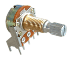
front view rear view Potentiometers used in the A-100
The A-100 potentiometers are available as spare parts with these values: 10K (A and B), 50K (A, B and C), 500k (B), 1M (A and B) with A = logarithmic (audio type), B = linear and C = inverse logarithmic (ususally for filter resonance controls used). For prices please look at theprice list. 
Trimming potentiometers are available normally only linear. Apart from that they are defined by the same parameters as normal potentiometers. ![]()
![]()
![]()
![]()


![]()
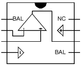
Single type 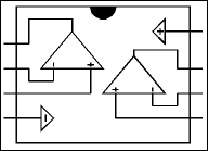
Dual type 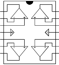
Quad type
Unused OpAmps (if e.g. only 3 devices of a quad opamp are used) have to be terminated in this way: non-inverting input has to be connected to GND, inverting input and output have to be connected (directly or even via resistor in the 1k...100k range). ![]()
![]()
![]()
![]()
![]()

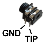
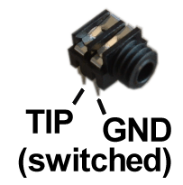
rear view front view jack sockets used in the A-100 ![]()
Inter-racial amplifier
-
So I acquired a Kenwood KR-7600. I tear it apart and look at the output
devices to see whats in there. Low and behold one channel is BJTs and the
other is ...
2 hours ago


0 comments:
Post a Comment